3D View
EZtrack displays real-time view of your virtual scene, displaying all the rigs you created, every offset that you applied and the referential points.
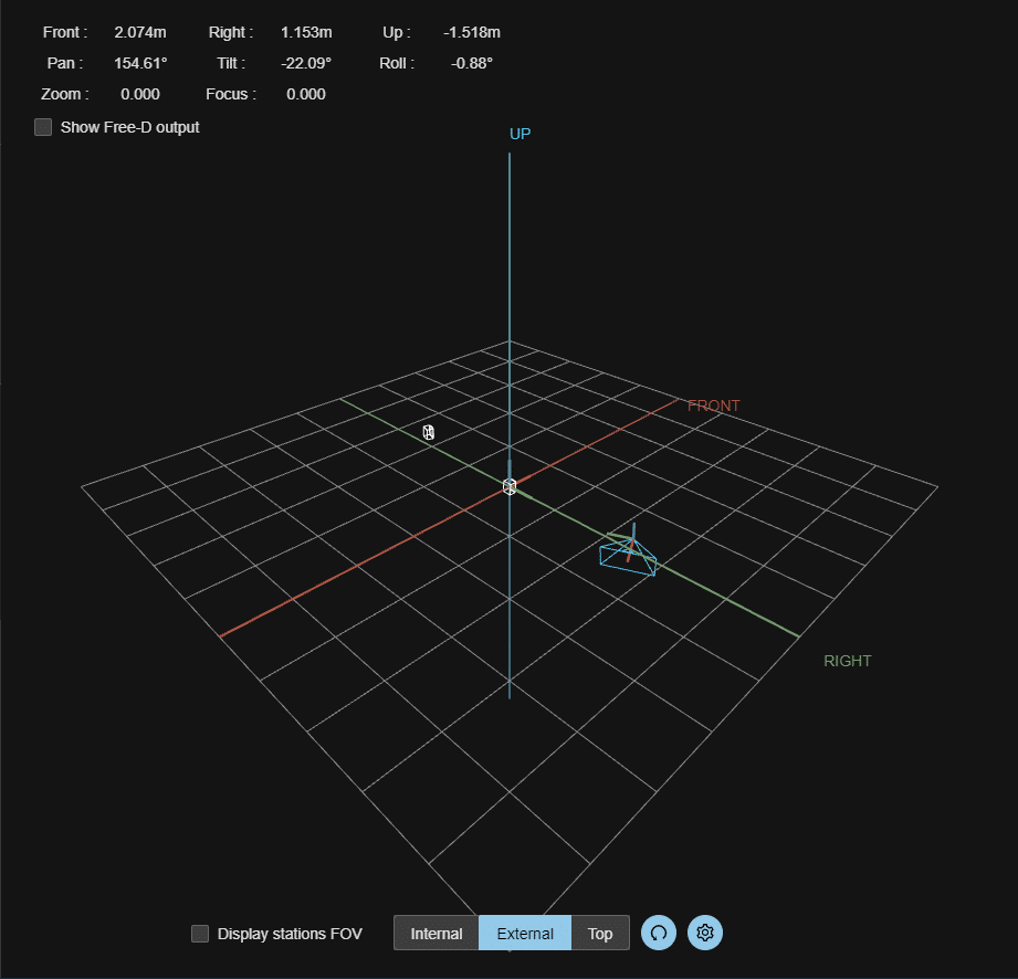
The space is scaled such that every grid cell is 1 x 1 meters.
Every rig is displayed as a pyramid, with its peak corresponding to the rig position, and the base showing its direction. A triangle indicator shows the current roll.
In the top-left corner is shown the position of the rig and the lens info.
1. Navigation
You can navigate into the scene by :
- holding right click and moving the pointer to move
- holding left click and moving the pointer to rotate
- using the mouse wheel to zoom in or out
2. Action bar
The checkbox on the left allows you to show the Field Of View of the base stations.
The buttons in the middle can be used to switch from an internal view (first person view, from the selected rig) to an external view (by default) or even a top view. Note that issuing movements while in “internal mode” will not move the camera, you are limited to the rig’s pose.
The refresh button on the right resets the point of view to the default position and orientation.
The cogwheel button on the far right can be used to display another submenu containing various options detailed in it's own section.
3. Rig Pose
Displays the position and orientation of the currently selected rig.
Can be toggled to display the position along coordinate system agnostic axes (Front, Right, Up) or using the selected protocol (Free-D or TCD) system using the “Show Free-D output” or "Show TCD output" checkbox. The orientation is displayed as the Euler coordinates “Pan”, “Tilt” and “Roll” (Similar to “Yaw”, “Pitch” and “Roll”). It also displays the lens information such as “Zoom” and “Focus” if your lens is linked to EZtrack.
If your rig is configured to use the TCD protocol, then more information on the lens will be displayed, such as focal length, focus distance, field of view etc.
Note
EZtrack uses meters as the unit of distance internally, but the Free-D and TCD values are displayed in millimeters.
4. Viewer Settings

At the top is displayed the list of rigs. Each row has two buttons. Clicking on the first one will switch between hiding and displaying the rig in question, whereas the second one will show the "Marker Edit modal" (detailed in it's own section).
Below are displayed 3 parameters :
- FOV: you can set the viewer's camera vertical field of view by setting this value
- Grid: you can choose to display or hide the grid by enabling this switch
- Axes: you can choose to display or hide the axes by enabling this switch
Those three parameters are saved between in the browser's cookies and will persist after a page refresh.
5. Marker Edit Modal
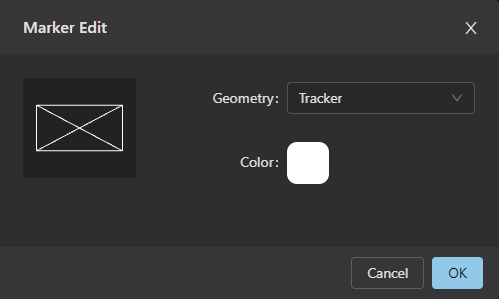
This window allows you to change the appearance of a rig when displayed in the 3D view. For this, you can use the geometry dropdown and the color picker. A preview of your selection is displayed on the left.
Note
A selected rig's marker will always be blue.