Lighthouse Panel
The Lighthouse panel allows the user to manage the list of lighthouse devices that are currently connected to EZtrack as well as setting a custom referential space or synchronizing two EZtrack referentials together.
1. Device List
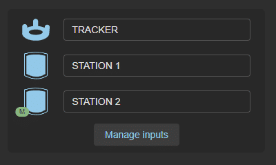
The top of the section is reserved for displaying the list of tracking devices connected to the system. Each row corresponds to a device, and displays an icon (corresponding to the device’s type) followed by it's name.
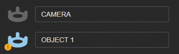
Depending on the status of the device, the icon will have different attributes:
- a blue icon means the device is connected and active
- a grey icon means the device is disconnected or inactive
- a red lightning bolt over the icon means that the battery of the device is getting low (less that 20%)
- an orange exclamation point sign indicates that the device cannot be located by the station at the moment
- a grey stop sign means the device is being calibrated and should not be moved
- a grey 's' sign means the device has an enabled clamp filter and is currently static
- a green 'm' sign next to a station icon indicates that the station is considered to be the "master"
Note
Devices will turn off upon falling at less than 3% of their battery capacity.
Hovering over the icon on the left will display information based on the device’s type; for a base station: it's channel number, for every other type of device (tracker, controller, swan): it's serial number and battery level. Each device can be renamed by clicking on it's name, changing it, and pressing the return key or leaving the field.
New devices can be added either by USB cable or Bluetooth connection.
- To add a new device using USB, simply plug it to the EZtrack box.
- To add a new device using Bluetooth, you need to plug a dongle to the EZtrack box for each device you want to connect, and click on the “Pair” button from the Settings -> Tracking. EZtrack will then accept connections for 10 seconds. During this time, press the button located on the middle of the tracker for approximately 3 seconds, until the led starts flashing.
2. Referential definition
By default, the origin of the EZtrack referential is the position of the main base station and the axes are defined by it's orientation and an estimated ground plane; however, there are several ways to redefine this referential: using a tracked device to set the new plane, orientation and origin.
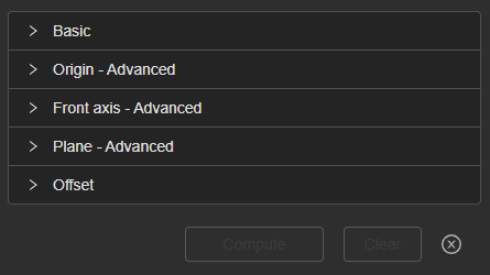
The **basic panel is used to set up the referential in a fast way, using 3 positions to determine the plane, front axis and origin of the new referential. Each of these three components can be determined separately by using the next 3 panels (labeled as “advanced”). These also allow you to override positions previously set using the “Basic” panel or add other positions to determine a plane or axis more precisely.
Clicking on the "Compute" button will calculate the new referential based on the different positions recorded. Clicking on the “Clear” button will remove every position previously saved (but won’t reset the referential to the default one). To Reset to the default referential, click on "Clear", then "Compute".
2.1. Basic
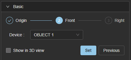
The basic panel is used to compute a new referential in 3 sequential steps, saving the current position of device at during each one.
The steps are displayed at the top, with the current one displayed brighter and the completed ones marked by a success icon.
The device used to record a position can be selected on the second row.
Clicking on the “Set” button will save the current position by averaging different positions during one second. The position will be used differently depending on the current step :
- Origin : the position will be used to determine the plane (using at least 2 other positions), the front axis (using at least 1 other position) and the origin.
- Front : used to determine the plane (using at least 2 other positions) and the front axis (using at least 1 other position)
- Right : used to determine the plane (using at least 2 other positions)
The “Previous” button can be used to remove the last position saved and return to the previous step.
Setting or removing a position here will also modify the advanced tabs accordingly (the basic panel being a shortcut to set the advanced information).
Note
For the front step, the device needs to be placed very precisely in the front direction, at least 50 centimeters away from the origin position. For the right position however, precision is not required, since it will only be used to determine the floor plane of the new referential and not it's orientation. Just be sure to put the tracker at least 50cm away from the origin position.
Checking the “Show in 3D view” box will display the different saved positions in the 3d view as crosses.
2.2. Origin
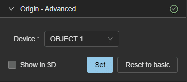
The “Origin” panel is used to determine the new referential origin.
If a position has already been saved, it will be displayed on the first row, with the name of the device used.
The device used to record a position can be selected on the second row.
Clicking on the “Set” button (or “Override”, depending on if an origin has been saved from the “Basic” panel) will save the position of the device as the origin of the new referential.
Clicking on the “Reset to basic” button will set the origin defined in the basic panel (if there is one) as the new referential origin. It is already the case if you didn’t override it previously.
Checking the “Show in 3D view” box will display the origin position in the 3d view as a white indicator.
2.3. Front Axis
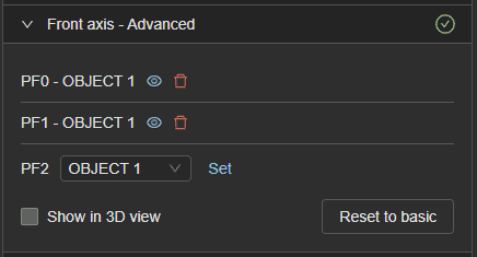
The “Front axis” panel is used to determine the new referential front axis (and right axis, by using the plane too).
Any number of positions can be recorded and will be displayed as a list at the top of the panel. All these positions will be used to average the front axis. Each item in the list is composed of the device used to set its position, a “highlight” button to highlight it in the 3d view, and a delete button to remove it from the list.
A position can be added to the list by choosing a device from the dropdown and clicking on “Set”.
Clicking on the “Reset to basic” button will set the origin and front positions defined in the basic panel as the new positions.
Checking the “Show in 3D view” box will display the positions in the 3d view as red indicators.
2.4. Plane
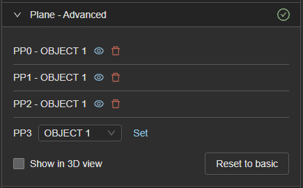
The “Plane” panel is used to determine the new referential floor plane.
Any number of positions can be recorded and will be displayed as a list at the top of the panel. All these positions will be used to average the floor plane. Each item in the list is composed of the device used to set its position, a “highlight” button to highlight it in the 3d view, and a delete button to remove it from the list.
A position can be added to the list by choosing a device from the dropdown and clicking on “Set”.
Clicking on the “Reset to basic” button will set the origin, front and right positions defined in the basic panel as the new positions.
Checking the “Show in 3D view” box will display the positions in the 3d view as blue indicators.
2.5. Offset
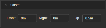
The offset panel provides a way of adding a static transformation (along the three axes) to the referential.
For example: if the referential has been computed using a tracked device at 50cm from the physical floor, the user can compensate this difference by adding a 0.5m offset on the “Up” axis. The referential will then be computed as if the positions recorded had been taken from the ground.
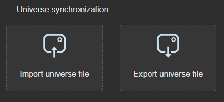
3. Lighthouse universe synchronization
This section provides a way of importing and loading a synchronization file in order to synchronize the tracking universe of several EZtrack systems.
On the left, it features an upload area that you can click or drag a json file to, in order to import a sync file from another system. Please note that this may drastically alter the rigs positions for 4-5 seconds.
On the right is a button used for exporting this sync file. When clicking on it, a synchronization file will be created and downloaded.