Rigs
1. Rig List

Displays the list of rigs. Each rig is represented as a tab.
Each rig features (from left to right):
- A status indicator. Blue if the rig is not sending any data, green if the configuration is valid and the communication has started or red if the communication failed due to invalid configuration
- It's name
- A rename button. Clicking on it will open a pop-up window with an input field to edit the rig’s name.
- A delete button. Clicking on it will remove the rig.
On the right of the rig list are two buttons used to create new rigs. The first (“+”) one adds a single empty rig to list. The second one (“++”) adds a rig for every tracking device connected and automatically adds the corresponding tracking node to it.
2. Rig
A rig defines an object to track, the data to send and how it should be sent.
A rig is composed of a list of transforms. These will be computed sequentially to determine the data packet to send to the render engine.
Example: A Transform node will set the orientation and position according to the chosen device pose. A Focus node would then set the focus field based on it's configuration. A static Translation node added to the end of the list would then modify the position that was computed (by the Transform node) by doing a translation of a defined value, etc...
The rig’s network and synchronization configuration is located just below the node list.
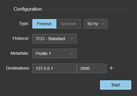
2.1. Configuration
Provides a way of configuring how the tracking data will be synced and sent over the network.
2.1.1. Type
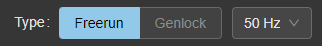
The type of sync to use for this rig, two types are available:
-
Freerun: the data will be sent based on an internal timer. A complementary dropdown can be used to choose the desired frequency (ranging from 25 to 360Hz).
-
Genlock: the data will be sent whenever EZtrack receives a genlock pulse input (This option is disabled if no genlock source is detected). The Genlock configuration is located in the Hardware Settings window.
2.1.2. Protocol
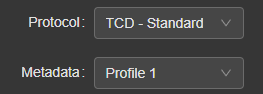
The data can either be sent as Free-D or TCD packets. You can choose which one here.
Below "Protocol", you'll be able to choose a metadata profile. Profiles allow you to choose the advanced data to send, they can be configured in Settings → Output metadata. The metadata profile will not be used if the rig is sending Free-D packets but needs to be set if you need to export this rig to fbx.
2.1.3. Destinations

Two fields define the IP address and port to which the tracking data will be sent. Another destination can be added by clicking on the "+" button, in which case another row will be added.
Clicking on the “Start” button will start sending the data to the configured endpoint(s).
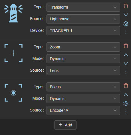
2.2. Nodes
There are 11 node types, each having different configuration requirements.
-
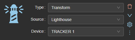
Transform : A transform node corresponds to a position and a rotation in the 3d space. It can either be set manually ("Static" source) or come from a connected tracker (other "source" options).
Example: To use the data coming from an Antilatency tracker, choose "Antilatency" as the source and the tracker in "Device" -
Zoom/Focus/Iris : Set the rig’s zoom, focus or iris value. Can be either “Static” or “Dynamic”. “Static” will set a value as the current rig’s encoder value, whereas “Dynamic” will update it based on the data sent by the lens connected to the system, a defined encodacam channel’s input or a Free-D receiver. Iris cannot come from a Free-D receiver.
-
Front/Right/Up translation : Translates the tracked device by a static or dynamic value on one of the 3 directions. Can be either "Static" or "Dynamic". "Static" will require a value in meters, whereas "Dynamic" will receive it's value from an Encoder channel or a Free-D receiver.
-
Pan/Tilt/Roll rotation : Rotates the tracked device by a static or dynamic value on one of the three axes. Can be either "Static" or "Dynamic". "Static" will require a value in meters, whereas "Dynamic" will receive it's value from an Encoder channel or a Free-D receiver.
-
Input : The node corresponds to the key of a ligthouse tracking device. Choose the tracker you want to read button presses from, and a list of keys will be available under the "Key" dropdown.
Due to the limitations of the Free-D protocol, the key's status will be sent either in place of the rig's zoom or focus field. You can choose which one will get overriden using the "As" selector.
Example
“device” is “TRACKER1”; “key” is “Power”; “as” is “Focus”. When the “Power” button located on “TRACKER1” is pressed, the rig’s focus is set to 1; otherwise, it is set to 0.
On a node's right side are a couple of action buttons :
- the delete icon is used to delete this node.
- the up and down arrows are used to move the node in the hierarchy. They are only visible if movement in this direction is possible.
- the cogwheel is used to display the node's settings.
- the paste icon is used to paste the copied node configuration to this node. The current configuration will be overriden.
- the copy icon is used to copy this node's configuration for pasting to another one. It is disabled if no config is currently copied.
- the more icon is used to toggle the display of the entire list of buttons. By default, only those that fit in the natural height of the transform will be shown.

2.2.1. Settings
There are 4 categories of settings that can be changed from this window, you can switch to each of these by clicking on the menu displayed on the left :
- "Filtering", which can be used to filter the data coming from this node. Useful if you experience jitter.
- "Timing", which can be used to add a delay to the specific node.
- "Inversion", which can be used to invert the sign of certain node values.
- "Ignore Data", which can be used to ignore part of the node's information, such as a position or rotation on an axis.
2.2.1.1. Timing settings
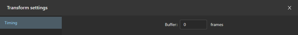
This window displays a field used to add a buffer to the node. For example, adding a buffer of 2 frames will make EZtrack use the node result computed 2 frames earlier when evaluating the rig data to send.
2.2.1.2. Filtering settings

This window allows you to configure a filter on the node. You can find more info on the filter here: https://gery.casiez.net/1euro/
Using a filter can be useful when dealing with heavy jitter, but it can cause a latency when moving a tracker. Finetuning the different settings is necessary to find a satisfying balance.
The first checkbox is used to enable the filter on the node, while the second one allows you to tune the filter parameters depending on the zoom values.
Position and orientation are filtered separately, and can thus be configured independently.
The three parameters are:
- static filtering frequency: decreasing this value reduces jitter but increases lag.
- derivative frequency: increasing this value will reduce the impact of the filter. This should typically stay at 1.
- latency compensation: increase this value when you notice too much movement lag. Typical values range from 0.001 to 0.01.
Static filtering frequency should be set first, with the goal of removing jitter while preserving an acceptable lag when moving slowly. Then, you can start tweaking the latency compensation to reduce this latency.
2.2.1.2.1. Adaptive filtering
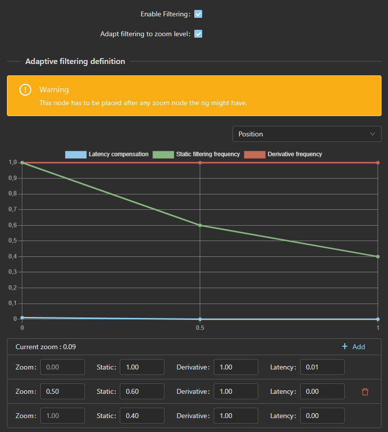
To get better results, you might want the filter effect to be stronger when zoomed in, since your camera would not be moving as much, but any jitter would be more impactful. To this end, you can enable the "Adapt filtering to zoom level" checkbox, which will display new curves. Please note that if using adaptive filtering, you should put your zoom node higher than your tracking node in the rig hierarchy.
Above the curves display, you can find a selector to choose between the position and rotation configuration.
Below the curves is the list of points that are set. Each point has an associated zoom value on a scale of 0 to 1, and the three filter parameters. Depending on the current zoom value, the filter will use parameters interpolated between the surrounding points.
Example
If 3 points are set at 0, 0.5 and 1 zoom, with respective static filtering frequency values of 1, 0.6 and 0.4, and the current zoom is 0.75, the current static filtering frequency used by the filter will be 0.5.
2.2.1.3. Inversion Settings
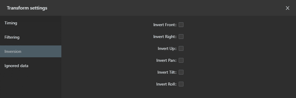
This window displays a checkbox for every value that can be inverted, depending on the node type.
For example, a "Zoom" node will have access to the "Invert zoom" parameter, while a "Pan" node will have access to its "Invert pan" counterpart. "Transform" nodes have access to every pose-related inversions. (X, Y, Z, Pan, Tilt and Roll)
Zoom, focus and iris values are not inverted. Instead, they are remapped to fit an inverted range. EZtrack uses the 0-65535 range internally, so those values would be remapped to the range 65535-0.
2.2.1.4. Ignore Data Settings
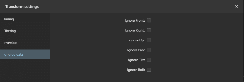
This window displays a checkbox for every value that can be ignored, depending on the node type. It is typically used if you know a tracking source cannot move on one of the axes and you can safely ignore what it is sending.
For example, a "Zoom" node will have access to the "Ignore zoom" parameter, while a "Pan" node will have access to it's "Ignore pan" counterpart. "Transform" nodes have access to every pose-related chekboxes. (X, Y, Z, Pan, Tilt and Roll)