Lens through External Encoders (Advanced)
Note
If encoding only for Zoom and Focus, the the basic external encoders setup should be preferred.
The workflow detailed below is a workaround to support Iris until a better solution is implemented. You can not use Zoom with this as there are only two encoder inputs on the hub.
1. Setup on camera
In this example setup, EZtrack is mounted behind a camera equipped with a cinema prime lens. There are two rings on the lens, one for focus and one for iris. Two external encoders have been installed on these to get both raw focus and iris data.
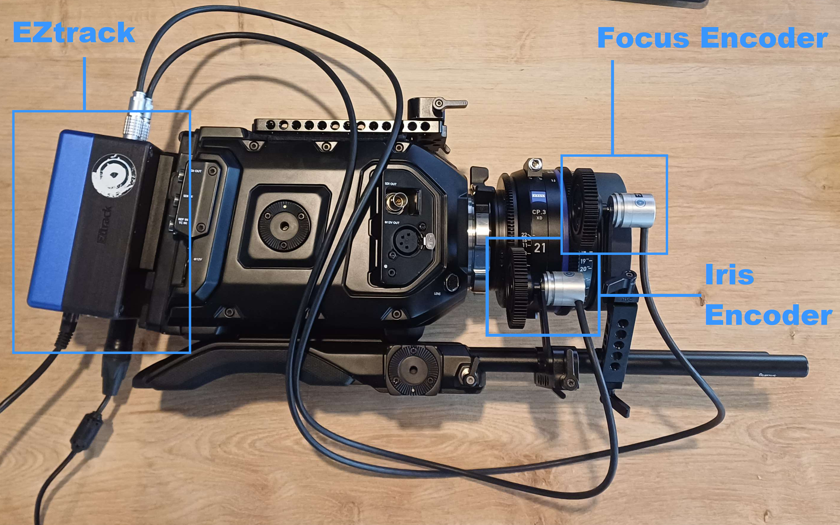
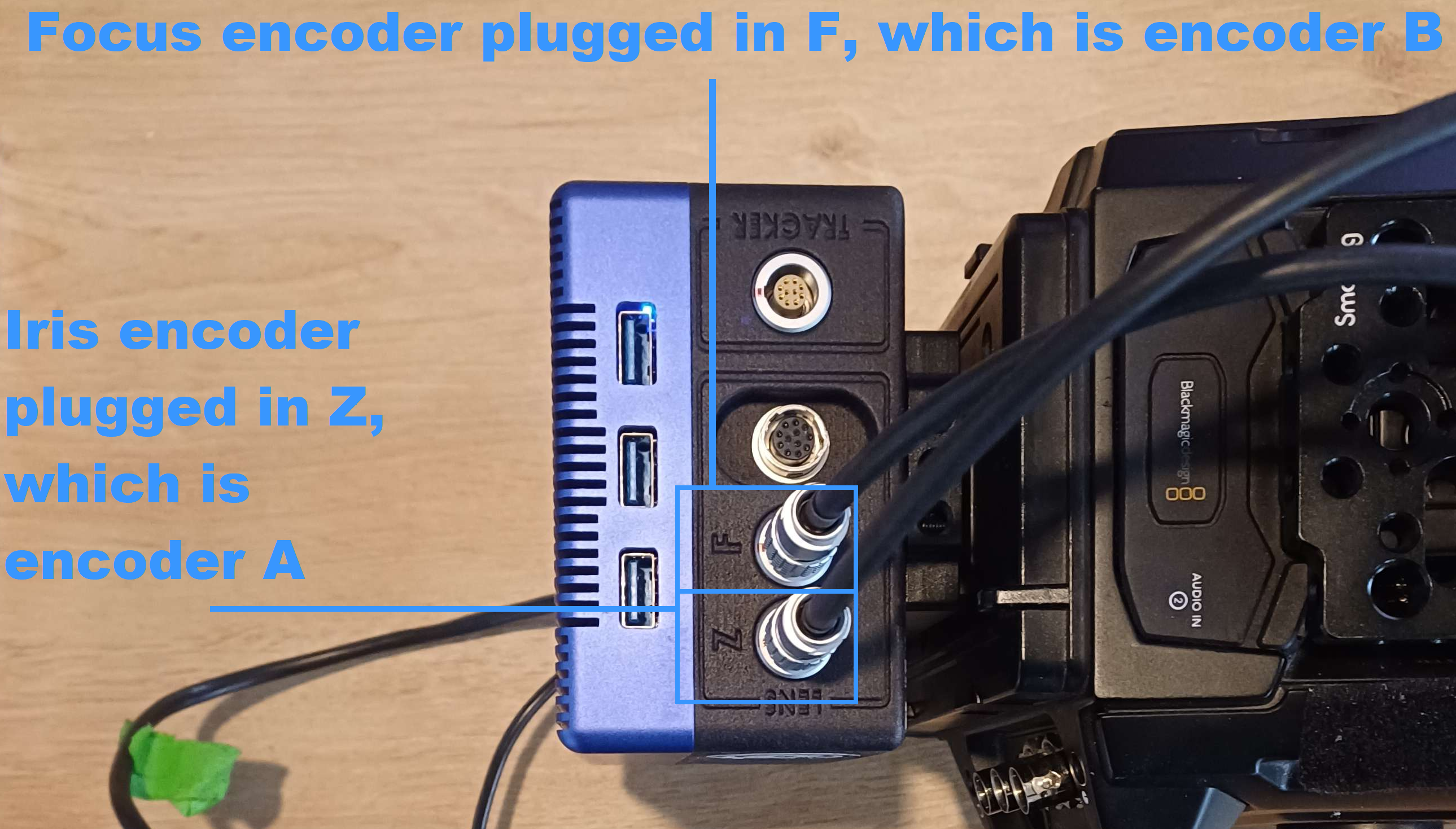
The Focus encoder is plugged in the "F" port on EZtrack, the Iris encoder is plugged on the "Z" port.
Note
The ports are named Z and F for Zoom and Focus, as this is the mapping used in the basic external encoders setup.
In the interface, you will see "Encoder A" and "Encoder B", they correspond to port "Z" and "F" respectively.
2. Rig setup
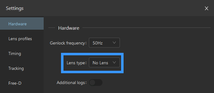
In the EZtrack Webapp, first of all, set the Lens Type to "No Lens":
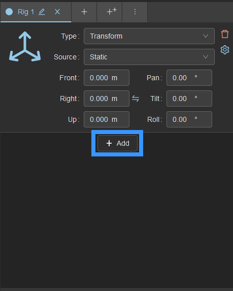
Then go to your rig. Before all lens nodes, you will have your tracking setup. For this example I just have a zero transform instead since I am only interested in the lens data.
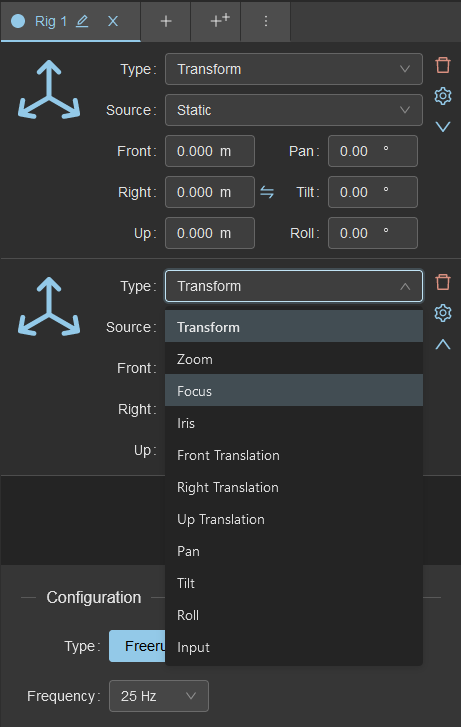
Click on the "Add" button:
Configure the rig element to Focus:
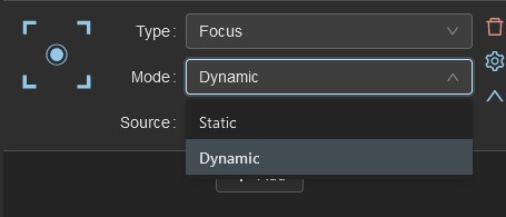
Set it to dynamic instead of static:
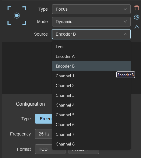
And set the encoder to "B", since our focus encoder is plugged in the "F" port:
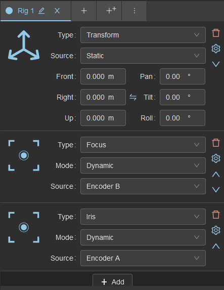
Do the same for Iris with encoder A and you should have something like this:
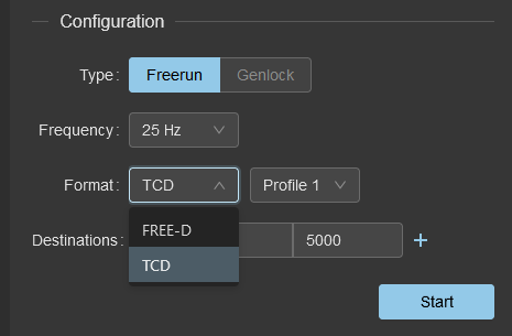
To view and send the Iris data, switch the rig to "TCD", and choose your profile if you have a lens calibration:
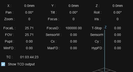
The data overlay over the 3D view displays some of the TCD data, you can expand it to show the calibrated values as well:
3. Set the encoder bounds
The rotary encoders can turn indefinitely in both directions, however we want to know where the course of the control on the lens barrel end.
In the basic external encoders setup this is handled automatically by going from min to max on the course of the lens, however since the pipeline we are using here as a workaround was designed for using encoders to do a kinematic model for motion, there is no such automation.
3.1. Understanding the advanced encoder pipeline
By default the values make little sense, as shown in the video:
How comes the raw value loops back to 65535 while the calibrated value goes negative ?
This is because of the encoder settings in the Hardware tab:
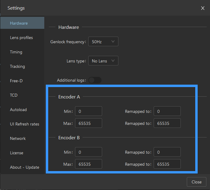
The looping back of the raw value is just a limitation of the display, it actually goes beyond but displays with a modulo.
The Min and Max set the bounds for a period of the encoder. The encoder is not bound so it actually continues counting outside of the interval. The remapping tells what values to give at each bound, but more accurately it tells by what ratio to scale the value, and this ratio will be used outside the boundaries as well.
3.2. Finding the root period
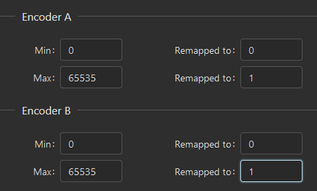
To test this periodic behavior, you can remap the Max to 1. This will count the number of 65535 periods you have passed.
Put the encoder away from the lens and operate it by hand. You will see as it turns the raw value go up or down indicating the number of periods passed. Notice how I was at 4 periods at the beginning, so way off the standard range.
Turning the encoder with your hand, place it in between 0 and 1 so that it displays 0. If you go into the negatives it will still display 0 so just after passing from 1 to 0, you can fine tune by mapping again to 65535 instead of 1 and target something near the middle like 30000:
Tip
When you power on the EZtrack hub, all encoders are put to 0 and it counts from there. This means you can avoid the part where you search for the root period by just plugging off and on the box power cable, do a few turns of the encoder in the increasing direction to get away from zero, then put it on the lens.
3.3. Setting the bounds of the lens ring
At this stage you should have put back the encoder on the lens and switched the remapping back to [0, 65535].
Go from min to max on the lens. For me I find: - Close focus : 50746 - Far focus : 37220
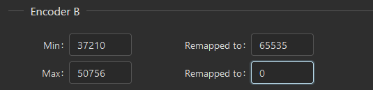
In the Hardware tab, change the min and max to the minimum and maximum values you found, regardless of the focus direction. In my case the focus direction is inverted, since for my lens profile I expect far focus to be 65535, so I inverted the remapped values.
You will notice as well on the image that I did not put exactly 50746 and 37220, but 50756 and 37210. This is a safety adjustment, so that if the encoder skips a tick or two it doesn't jump to the other side by periodicity. By adding ten ticks of safety on each side, the error introduced is minuscule. This kind of adjustment is done automatically in the basic external encoders setup by detecting overflows and increasing the bound instead of having a static buffer like here.
Now if you go from min to max on the lens, you will see the raw value go from roughly 0 to roughly 65535, and hopefully the calibrated value underneath from the lens file should be the expected one:
The test lens file mapped the focus linearly from 0 to 10000. We see the expected values.
You can do the same procedure for Iris.