1. Introduction
There is a limit to how refined and realistic real-time graphics can look. Affording sometime after a shooting to improve it with an offline render and post-production can take a scene from looking like a video game to a believable result, as well as more flexibility to tweak the animation, environment and match lighting.
Usually, a lot of work in post-production is dedicated to reverse-engineering data, especially with match-moving. However, during a virtual production shoot, a lot of this data is generated and validated on set. If the tracking data is propagated to post-production, the artists may have as little to do as launch a path-traced render in their 3D software to improve the realism of the result tremendously.
Some camera tracking systems, including EZtrack, are capable of recording tracking data during the shooting. The most common output format is FBX. This article will present how such data can be used to speed-up a post-production workflow.
Blender is increasingly becoming a staple of the VFX industry for smaller studios and productions. Being free and having a huge community, most 3D artists have at least some experiences in Blender, even if they work on other software. The concepts presented in this article can be adapted to all other 3D software.
2. Handle Timecode in Blender
Contrary to other VFX software like Houdini, Blender does not handle Timecode in the timeline, it only understands frames. In addition to this, there is a hard limit to the frame number: 1,048,574. This limit is lower than the maximum number obtained when converting a time code to frames. This means the Blender timeline can’t be used for an absolute Timecode workflow.
It is however still just as effective as other software for VFX, if you accept to use a relative workflow. This means the reference for the timeline of a shot is the beginning of the video plate.
2.1. Theory
Let the timecode be “h : m : s : f “, respectively the hour, minute, second and frame.
Fr is the framerate, for example 24 fps. We assume Fr is an integer. Floating point framerate has a more complicated method of conversion with drop-frames.
F is the frame in an absolute time timeline corresponding to the Timecode:
F = ((h × 60 + m) × 60 + s) × Fr + f
2.2. Application
Before doing anything in Blender, we need to know the Timecode of the start of the video plate. This can be obtained from the metadata of the video file depending on the format. Blender cannot give you this information as far as we know.
You can get it from a dedicated compositing or montage software. A good open-source option is Natron (https://natrongithub.github.io/)
2.2.1 Retrieve Starting TC using Natron
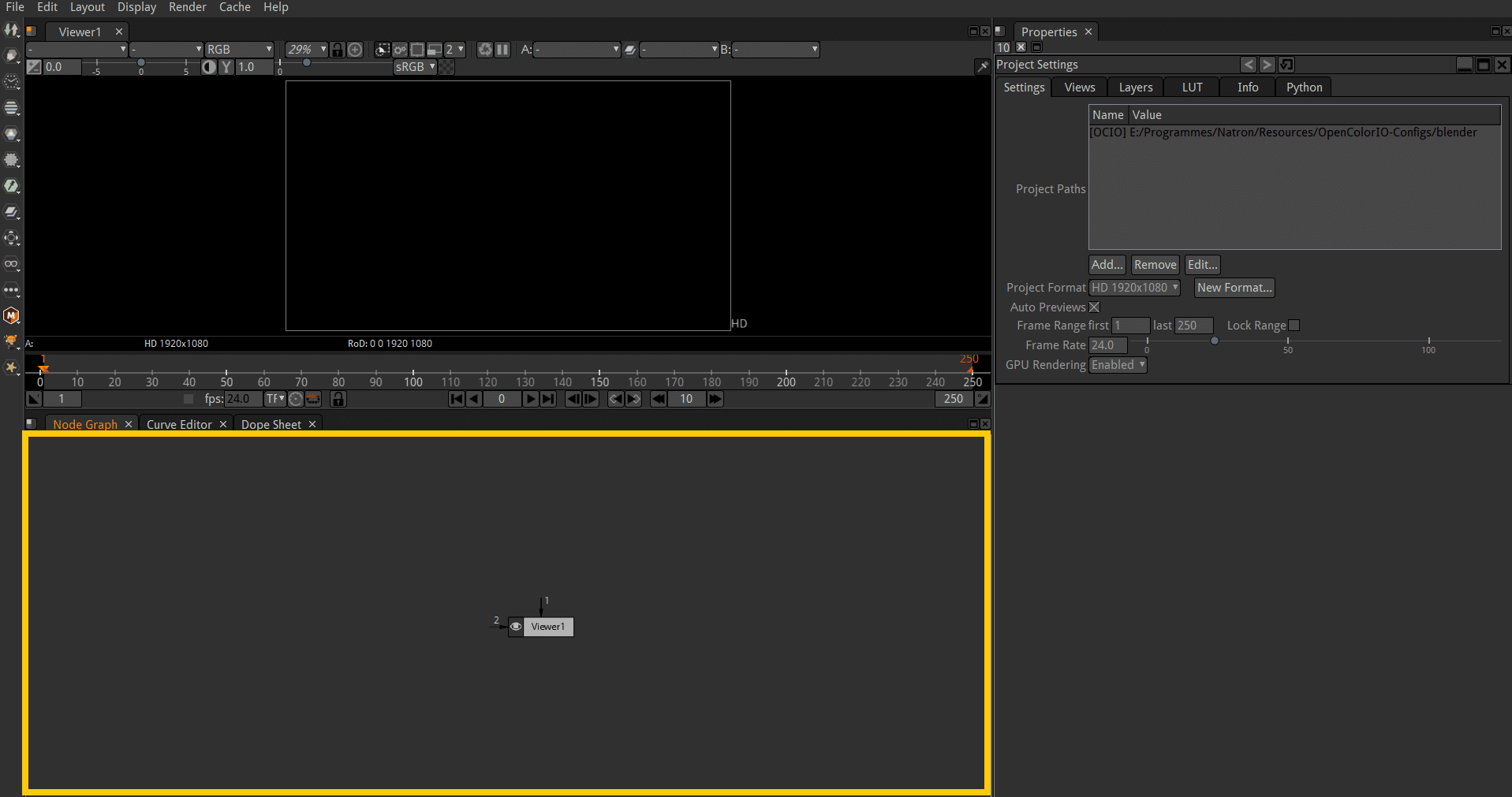
Drag and drop the video footage in the Node Graph. In the section on the right, details for this node are displayed. Click on “File Info…”:
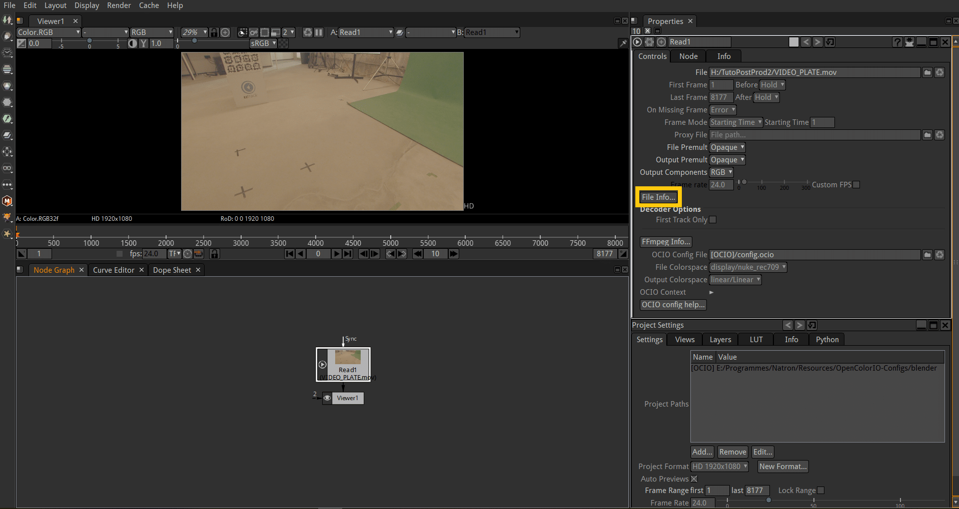
Scroll through the metadata a little until you see the starting Timecode:
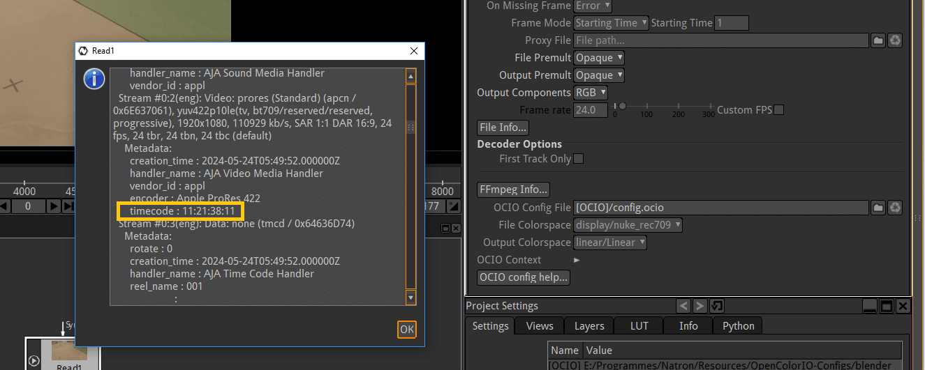
For this example, the video starts at 11:21:38:11.
In addition to this, you have confirmation that the video was shot at 24fps.
2.2.2 Convert the TC to frames
If we apply the formula above, we get:
F = ((11 × 60 + 21) × 60 + 38) × 24 + 11
F = 981563
3. Import the FBX file in Blender
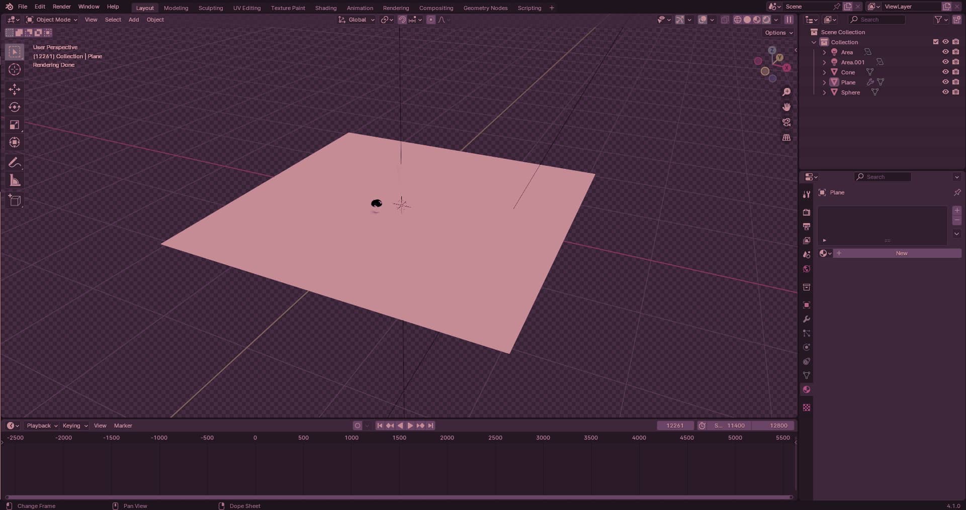
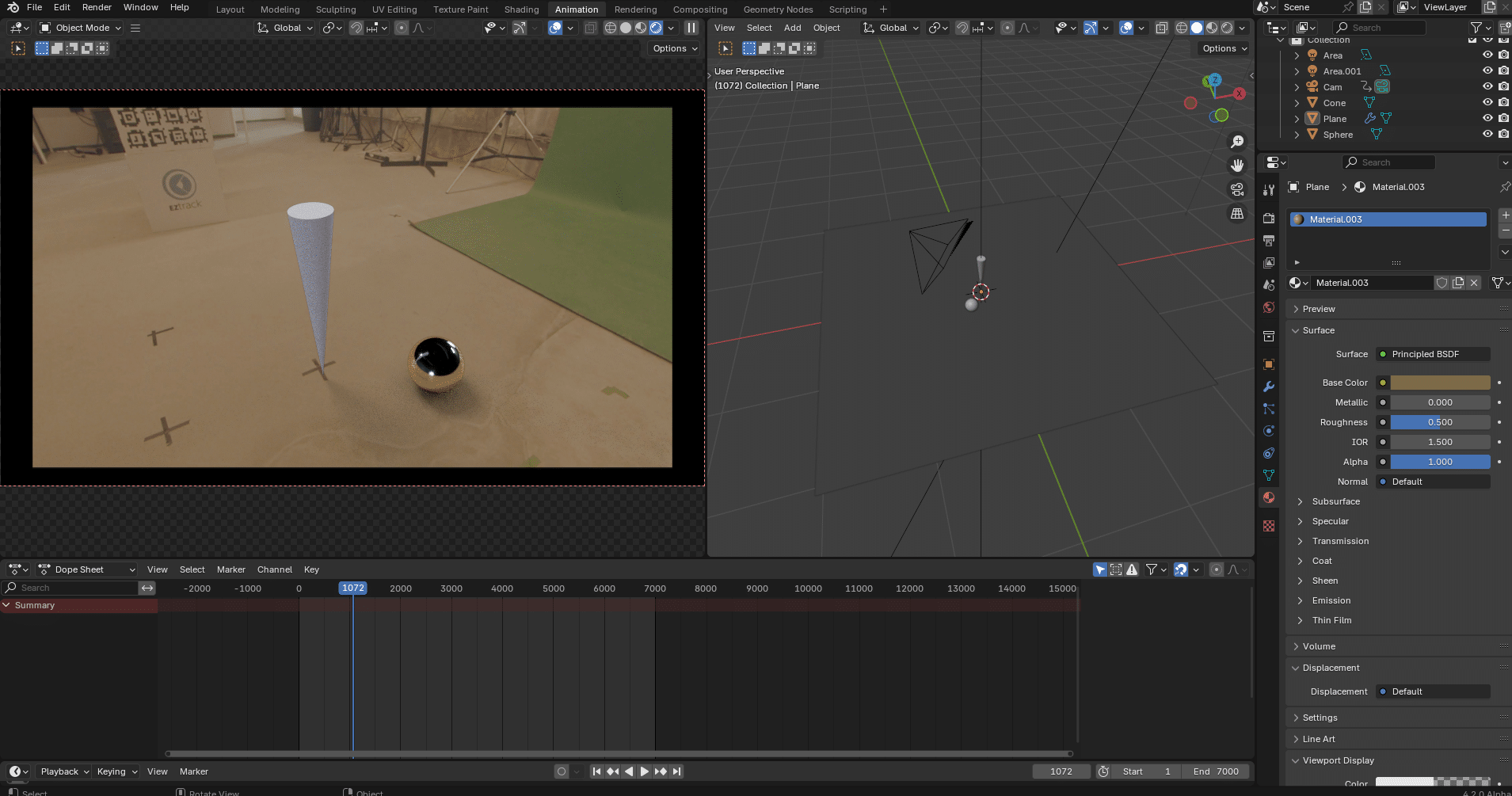
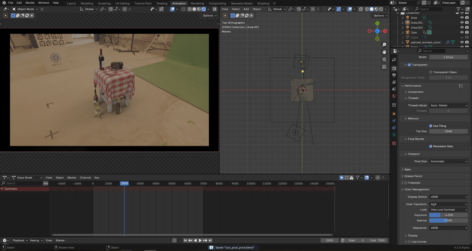
Currently we have this scene in Blender, with some CG objects, some lights, a shadow catcher and an HDRI of the set loaded:
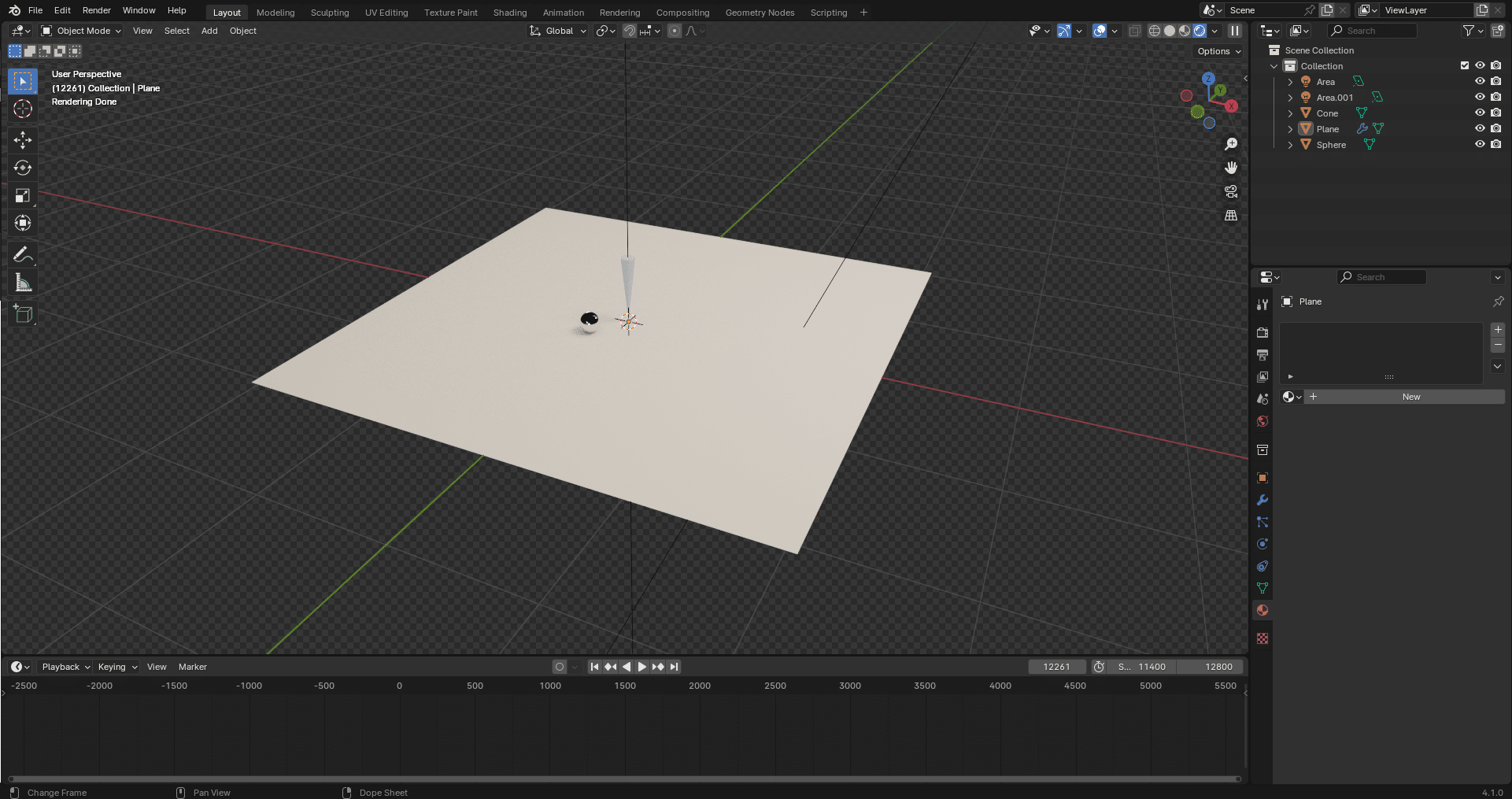
In a virtual production workflow where Unreal is only used for pre-visualisation, this should be your master scene and would be equivalent to the Unreal scene in terms of layout, but with higher quality assets, materials and eventual simulations.
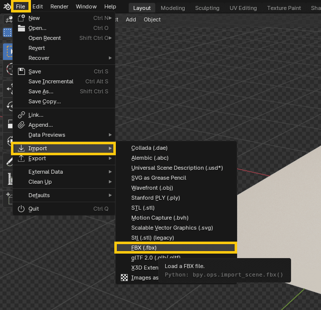
In addition to the video plate, we have a tracking FBX file. To load it in the blender scene, got to File→Import→FBX:
In the FBX import window, select the file corresponding to the video take, but do not press “Open File” just yet! Look to the right in the options and open the “Animation” tab:
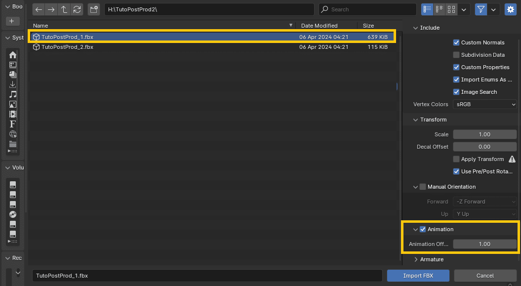
This is where you will be able to offset the tracking so that it lines up with the video.
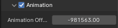
In the “Animation Offset” field, input minus the frame number obtained from the video Timecode. This will offset the frames of the FBX by that amount, so that the animation starts at the same time as the video plate:
Now, press “Import FBX”. A camera new is created with animation curves:
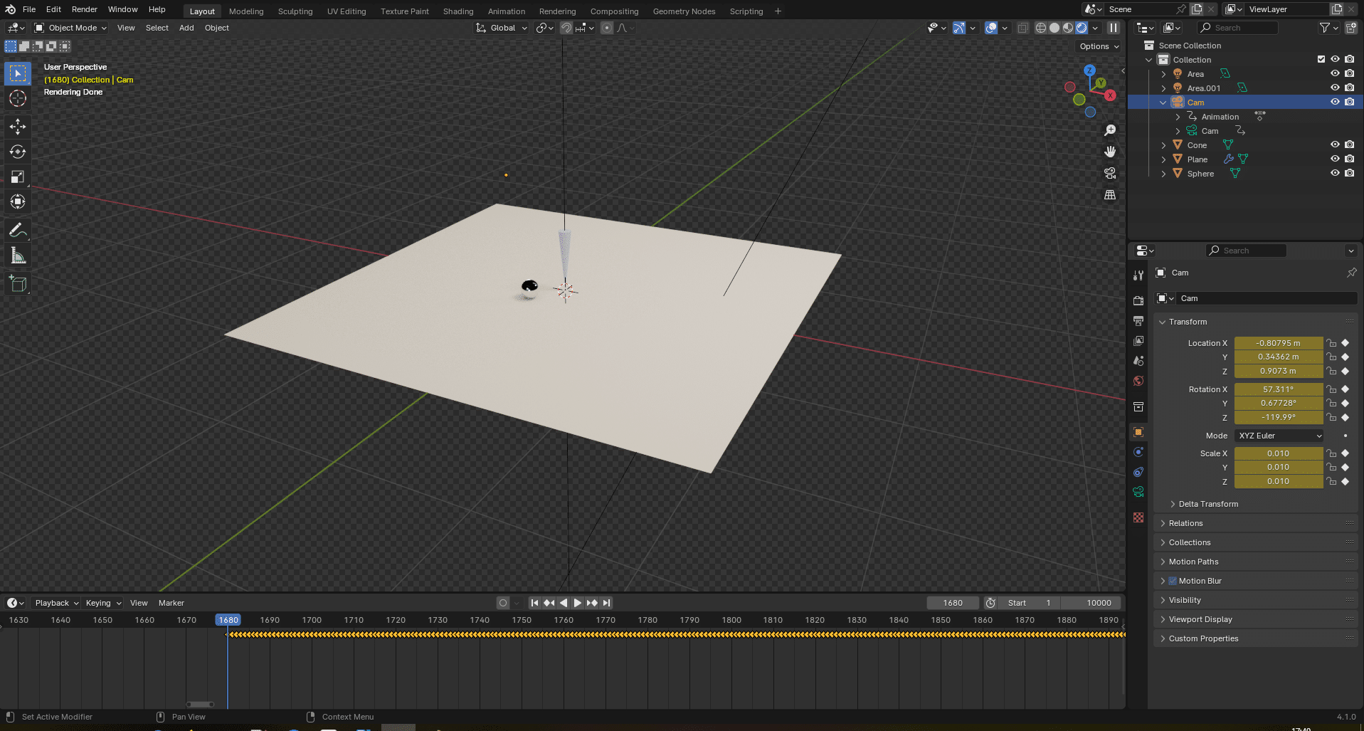
Here, the keyframes start after frame 1, which means the FBX recording was started after the video recording. This is normal, since the triggering process is manual. This means the camera operator started his recording before the tracking operator. If it was reversed, the tracking would be cropped to start at the same time as the video. Note that in any case, the actual action should begin after both have started recording.
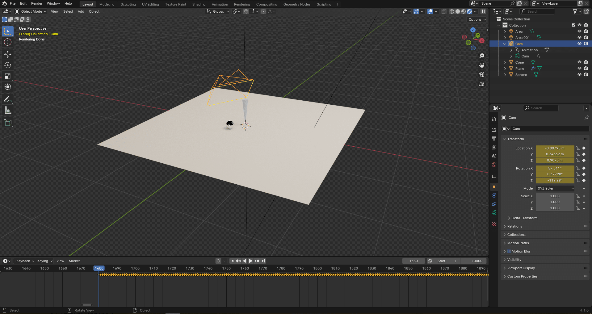
The camera looks quite small though. The Blender implementation of FBX has issues with some scalings, but it can easily be fixed. With the camera selected, right click on the scale attributes and press “Clear Keyframes”. This will remove all scaling animation on the camera and allow you to manually set the scale to your liking. This only affects the display of the camera in the viewport:
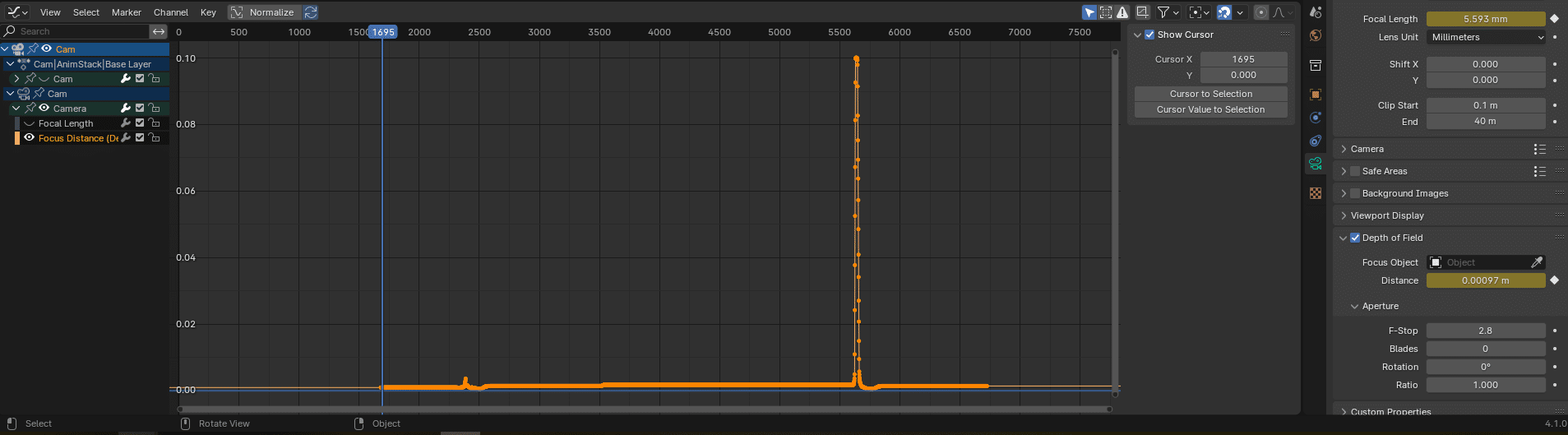
In addition to position and rotation, the camera should have keyframes on the focal length and the focus distance:
Similarly to the camera scale, the focus distance is much too small as Blender interprets metres as millimetres.
Add an Envelope modifier with a control point at frame 0 that maps from (min=0; max=1) to (min=0; max=1000), effectively converting the focus distance from metres to millimetres:
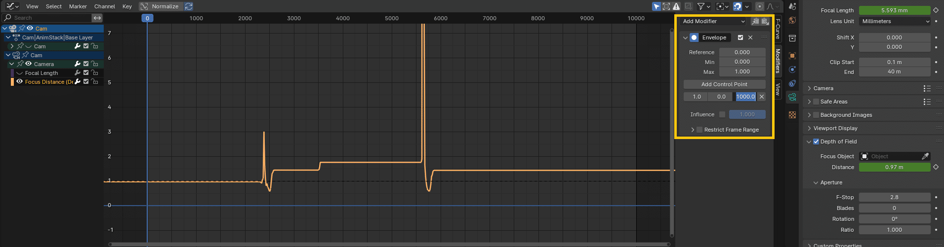
Now the tracking data is physically consistent and should line up with the video footage.
4. Use the Video Plate as Reference Background
You can use the video file as reference background in the virtual camera. This video MUST BE UNDISTORTED before being used as a reference, otherwise things will not line up when applying the distortion on the CG. See the article Post-Production & image compositing: distortion/undistortion in the Blender Compositor for details on applying distortion and undistortion ST-maps in the Blender compositor if the video plate is not undistorted yet.
4.1 Undistort and prepare overscan
For this example, the compositing graph looks like this:
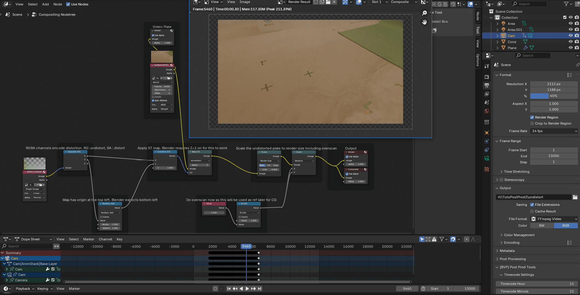
The ST-Map format here is a bit different to that presented in the aforementioned article.
The principle is the same, but both the distortion and undistortion maps are baked into the same file using the RG channels for undistortion and the BA channels for distortion mapping. This is a bit more compact, but both conventions (2 RG maps or one RGBA map) exist.
Note the 1.1 overscan value applied at the end to scale the image down. This is compensated by a higher render resolution in the output settings on the right. When distorting a CG render, pixels may need to be fetched from outside the rendered area. This is why when doing VFX the render is always larger than the desired resolution to be able to retrieve these pixels in final compositing. This is overscan.
Blender does not handle overscan natively, so we must create it ourselves by increasing both the render resolution and the sensor size of the camera. Scaling the reference footage according to overscan after undistorting will allow us to directly put it as background in the camera bigger sensor without worrying about it later.
The whole sequence is rendered out. At this stage you can render to mp4 or reduce the render resolution scale if needed, since this will only be used as reference. The format shouldn’t lag the in-camera live preview afterward.
4.2 Load the video as camera background
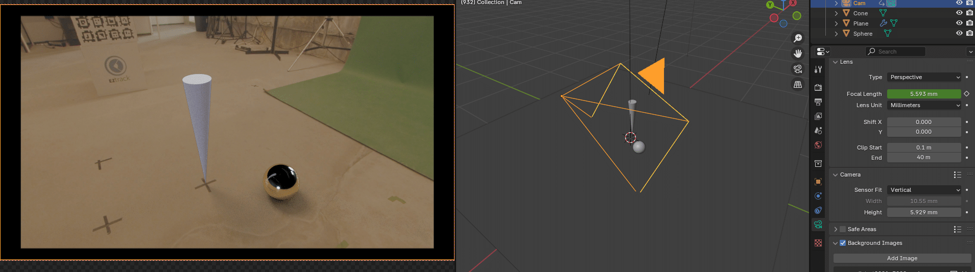
With the camera selected, in the camera settings panel, check “Background Images” and press “Add Image”:
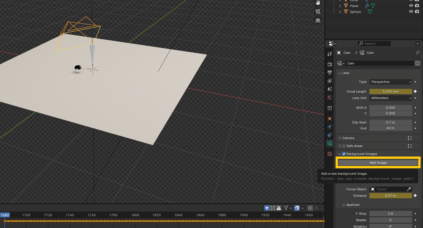
Select your undistorted video file and adjust the number of frames if needed.
Then in the “Animation” workspace, select the FBX camera as the active camera and enable “show overlays”:
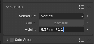
Already this seems to line up quite nicely, but there is still an offset to take care of. Remember how we added overscan on the undistorted plate ? We need to add it to the camera sensor size as well. For now the camera sensor is the exact size, as configured in the tracking system, but we need to scale it by 1.1 here to match the overscan:
The camera field of view is now coherent with the added overscan:
From there, the camera and lens poses match the video and the scene can be rendered, or artistic adjustment made.
5. Artistic adjustments
These steps are completely optional but can help make a render look more realistic.
5.1 Accurate reflections with UV projection
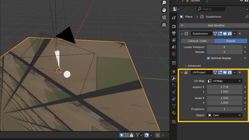
Now that we have the camera in the scene, we can use it to project the video on CG elements, like the shadow catcher, for more accurate reflections.
In the material of the shadow catchers, load the undistorted video plate as an animated texture and plug in in the albedo and eventually some emissive. Add a UVProject modifier on the shadow catchers with the camera selected as projector. Change the aspect ratio to match that of the camera:
5.2 Refine the scene
The pre-visualisation layout may not have been of final quality. Using the video as reference the scene can be tweaked to better match the artistic vision and better integrate the virtual and the real. So tweaking the lights, adding other assets, simulations, changing materials etc…
3D models courtesy of Polyhaven.com
5.3 Match the blurs
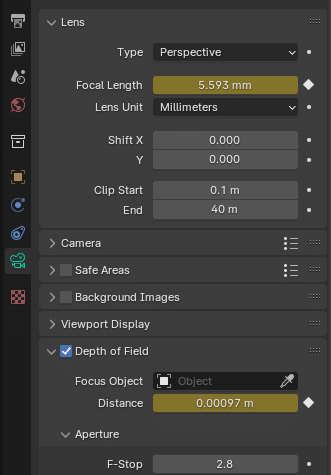
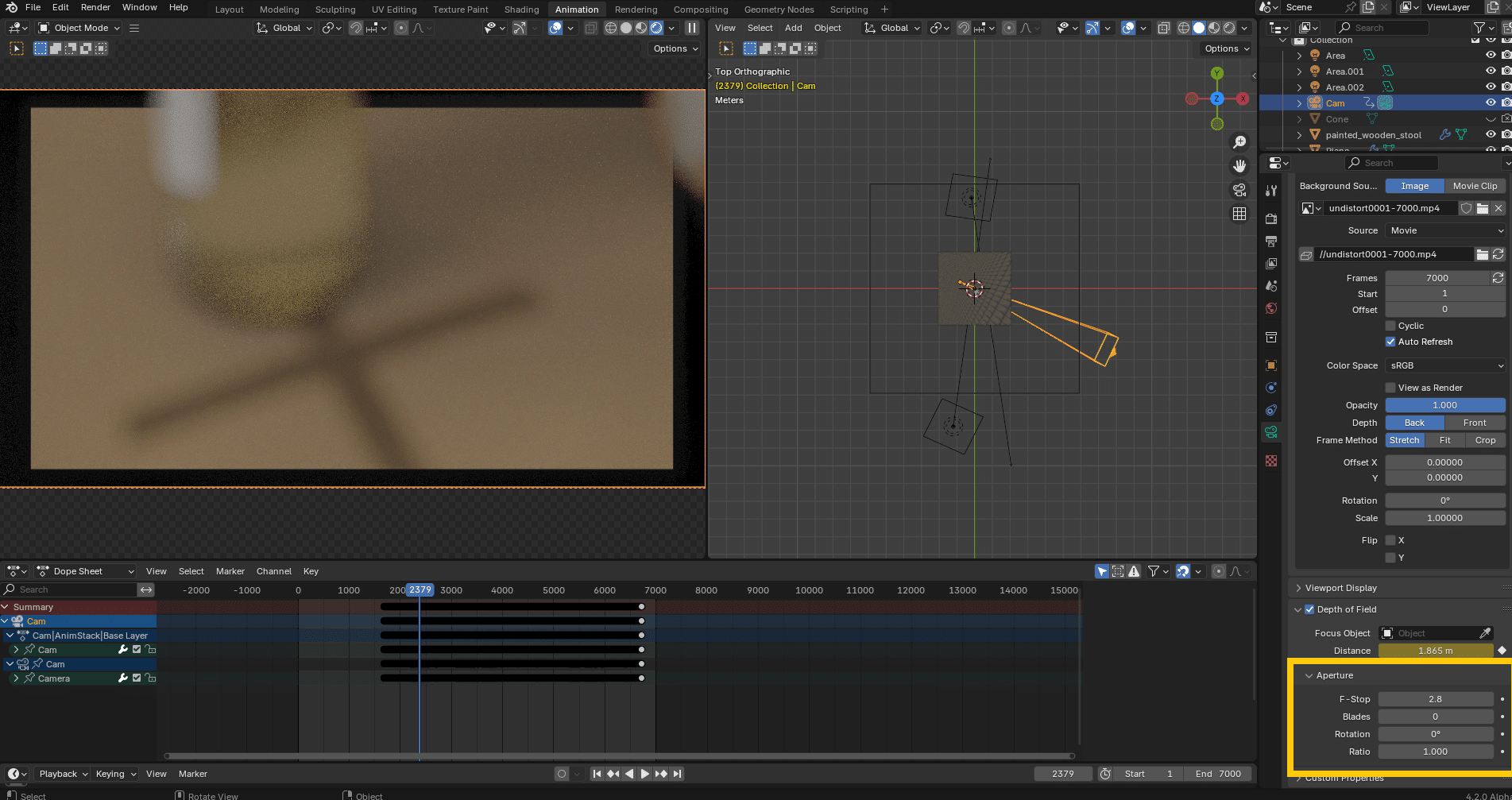
Another important thing to tweak to ensure a good integration is the look of the depth of field. Even if the focus distance is correct, the amount of blur and the bokeh shape can give away the CG.
Here we just copied the 2.8 f-stops from the lens barrel and left the default circular bokeh, since it gave good enough results. Sometimes you may have to change the f-stops number a bit compared to the real value to match the blur visually:
Another blur to match is the motion blur. Here we put a shutter of 0.5 in Cycles to replicate the 180° shutter of the real camera.
6. Render out the sequence
From there you can start the render. Render just the CG with a transparent background as an image sequence with high bit depth and transparency, to keep as much latitude as possible in compositing afterward.
See the article Post-Production & image compositing: distortion/undistortion in the Blender Compositor for details on applying back distortion to the CGI so that it can be composited with the original distorted video plate.