1. Introduction
The Eztrack Ecosystem works well together, making it easy to transfer data between CalibFX® Lens, CalibFX® Lineup, EZtrack and the EZtracking plugin for Unreal. However, it is sometimes desirable to only use the calibration software when building custom pipelines, or have better interoperability with other ecosystems.
For this example, we will configure a PTZ camera using CalibFX® Lens and CalibFX® Lineup, but apply the result using only the native Unreal plugins.
2. CalibFX® Lens
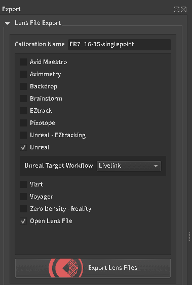
After completing the lens calibration, export the result for both Unreal Livelink and Open Lens File.
![]()
This will output two files, a .json file for CalibFX® Lineup and a .ulens file for Unreal Engine.
3. CalibFX® Lineup
The Json file is loaded in CalibFX® Lineup. The PTZ currently sends FreeD data to the computer on port 5002, so the receiver is configured as such.
For a PTZ, taking about 6 pictures in the corners of the image doing pan and tilt motions is enough. After solving, we get the Referential and Tracker offsets : 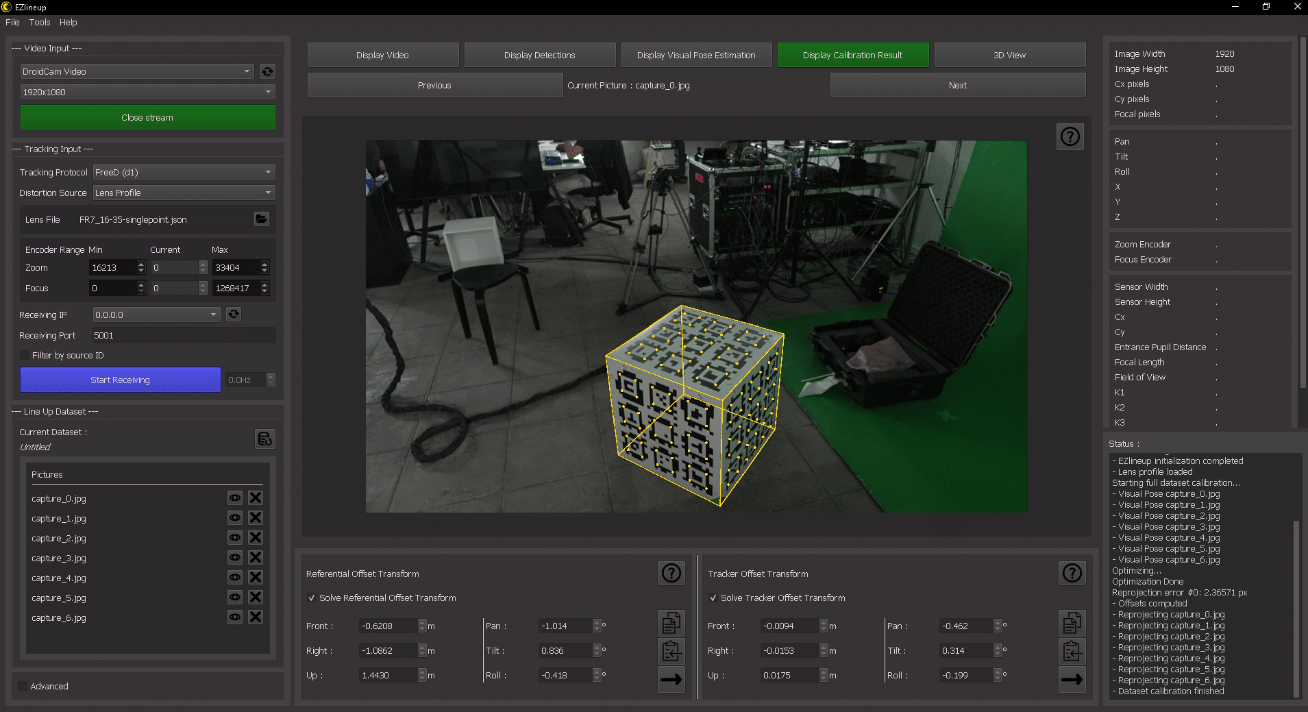
The reprojection of the cube in « Display Calibration Result » uses both the tracking, the lens file and the computed alignments. It should be strictly equivalent to a reprojection of the cube in Unreal Engine in the same pose if the workflow is correct.
4. Unreal Engine
4.1. Install the plugins:
– Livelink FreeD, to receive tracking straight from the PTZ
– Livelink Lens
– Lens Calibration
– Timed Data Monitor
– Composure
4.2. Livelink Input
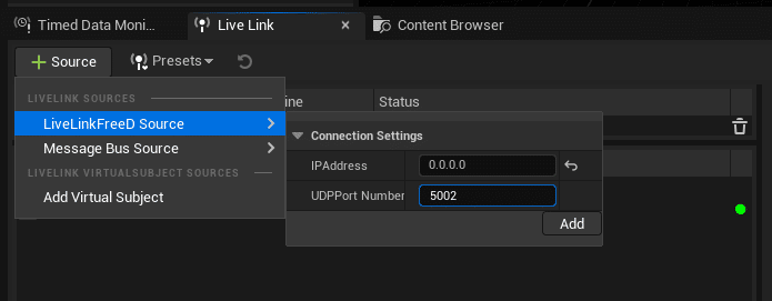
The PTZ is sending to the computer on port 5002. Make sure to shut down the receiver in CalibFX® Lineup to free up the port for other applications beforehand.
We create a LivelinkFreeD Source with IP 0.0.0.0 and port 5002. IP 0.0.0.0 means we listen on all network interfaces available.
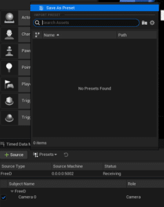
To avoid having to do this at each startup, create a new Livelink Preset :
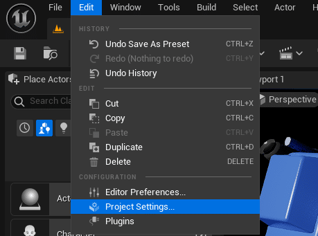
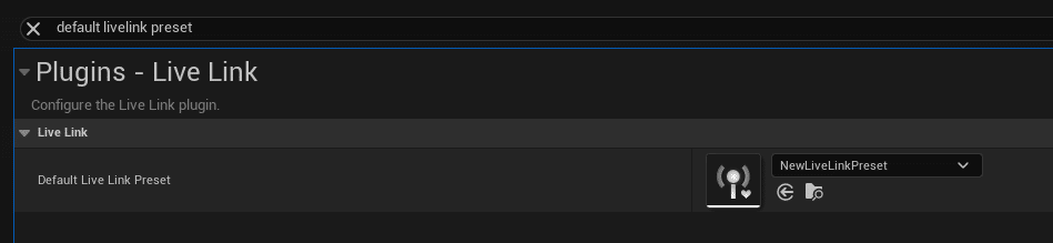
Then go to the Project Settings and set the Default Live Link Preset to the preset you just created :
Now we have a livelink subject called « Camera 0 » available.
4.3. Prepare the scene hierarchy:
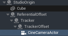
Studio Origin :
This referential is defined by the CalibFX® Lineup cube in the studio.
Objects that represent or interact with real elements should go under here.
Cube :
This is just a cube matching the CalibFX® Lineup
cube.
It can be used for debugging to check that the reprojection is correct.
Usually this actor would be hidden in production.
Referential Offset :
Goes from the cube referential to the tracking referential. For a PTZ, that would usually be the center of the tilt axis.
Tracker :
This is where the transform coming from tracking is applied. In the case of a PTZ you would only get pan and tilt here.
TrackerOffset :
Goes from the tracker referential to the sensor referential.
CineCameraActor :
Does the actual rendering, this is where the equivalent pinhole camera would be placed in the system. Note that in general this pinhole camera has to be placed in front of the sensor, at the lens entrance pupil. The entrance pupil offset (also called nodal offset) is given by the lens file and applied here
4.4. Studio Origin
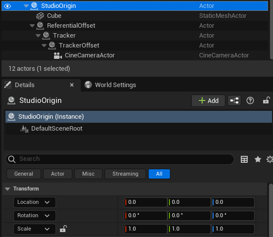
In this example it is at the origin, but you can move this actor however you want to move the studio in the virtual scene, as long as all CG objects related to real objects are parented to the studioOrigin.
4.5. Cube
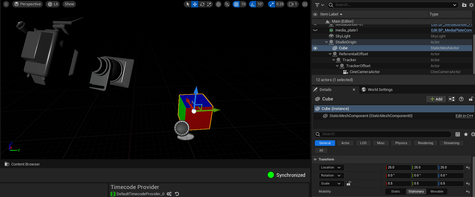
Position : (25, 25, 25)
Rotation : (0, 0, 0)
Scale : (0.5, 0.5, 0.5)
For this example we have given it a translucent material colored with the absolute value of the vertex normals to have an easy overlay in composure.
4.6. Referential Offset
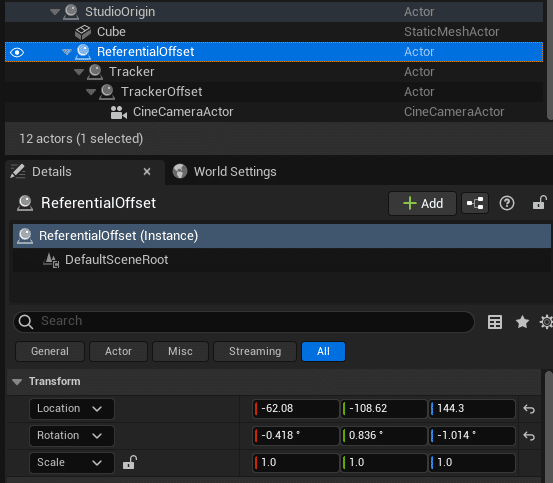
The Referential Offset from CalibFX® Lineup goes here. The mapping is as follows :
Front → location X
Right → location Y
Up → location Z
Pan → rotation Z
Tilt → rotation Y
Roll → rotation X
4.7. Tracker
![]()
Add a LiveLinkComponentController on the Tracker actor and select the livelink subject we created, « Camera 0 ».
Now you should see the transform of the Tracker actor’s sceneRoot change when the camera moves :
![]()
4.8. Tracker Offset
![]()
The Tracker Offset from CalibFX® Lineup goes here. The mapping is the same as for Referential Offset:
Front → location X
Right → location Y
Up → location Z
Pan → rotation Z
Tilt → rotation Y
Roll → rotation X
4.9. Cine Camera Actor
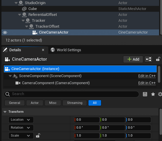
The transform of the CineCameraActor should be zero, both in rotation and translation.
4.9.1 Camera Livelink Component
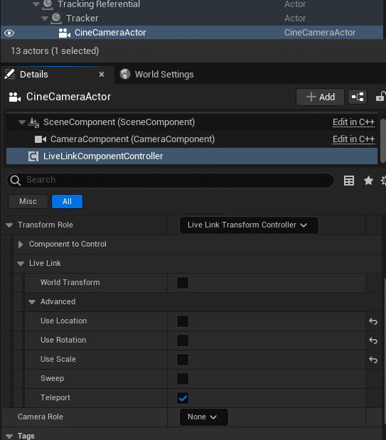
Add a LiveLinkComponentController on the Tracker actor and select the livelink subject we created, « Camera 0 ». However unlike the Tracker actor, we don’t want the camera position to move with livelink here, so in Transform Role → Live Link → Advanced, uncheck « Use Location », « Use Rotation » and « Use Scale ».
This livelink component will only be used to retrieve the lens data.
4.9.2 Camera Lens Component
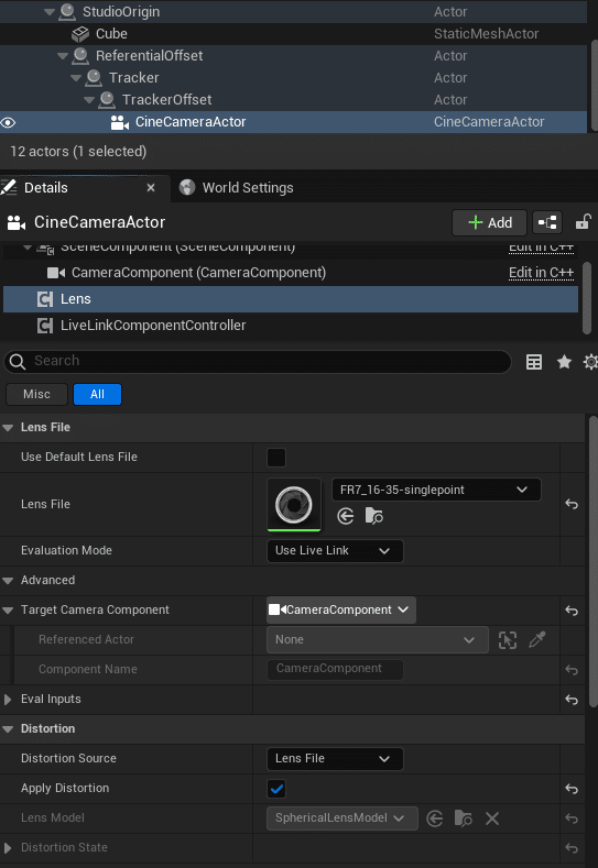
Add a LensComponent to the camera actor.
Drag and drop the .ulens file in the content browser and load the resulting asset in the Lens File slot. Evaluation mode is « Use Livelink ».
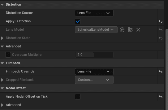
Make sure to select the lens file as distortion source and enable distortion. Filmback override should be set to « Lens File » as well. This will pull the camera sensor size from the lens file.
Normally « Apply Nodal Offset on Tick » should be checked, however there is a bug in Unreal that prevents using this currently. So we uncheck it and do a workaround in the level blueprint instead for now.
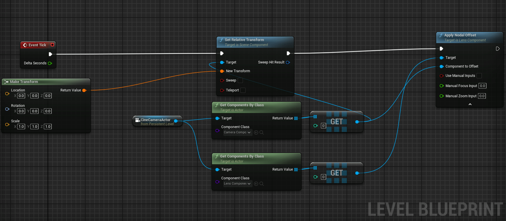
As a workaround, we apply the nodal offset manually at each game tick in the level blueprint.
We get both the Lens and Camera components form the target CineCameraActor and use the builtin « Apply Nodal Offset » node. This node is tricky to use because it will add the nodal offset at each tick instead of replacing it. We can’t only apply it at beginPlay either because the nodal offset varies with zoom.
So here we reset the cameraComponent’s transform before applying the nodal offset.
Note that this workaround only works in play mode, as event ticks are not triggered in the editor.
4.10 Media Profile Setup
We need to get the video into and out of Unreal. For this we will use the built-in Mediaprofiles.
4.10.1 Media Profile Setup
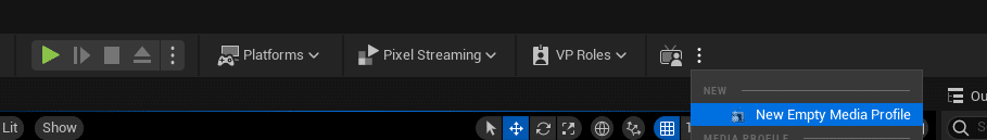
Create a new media profile if there is none currently. Media profiles are interesting over using media sources and outputs directly because it abstracts the proxy handling and has all the media configuration in one place.
For this example we configure the new MediaProfile to have one input and one output.
4.10.2 Media Profile Setup
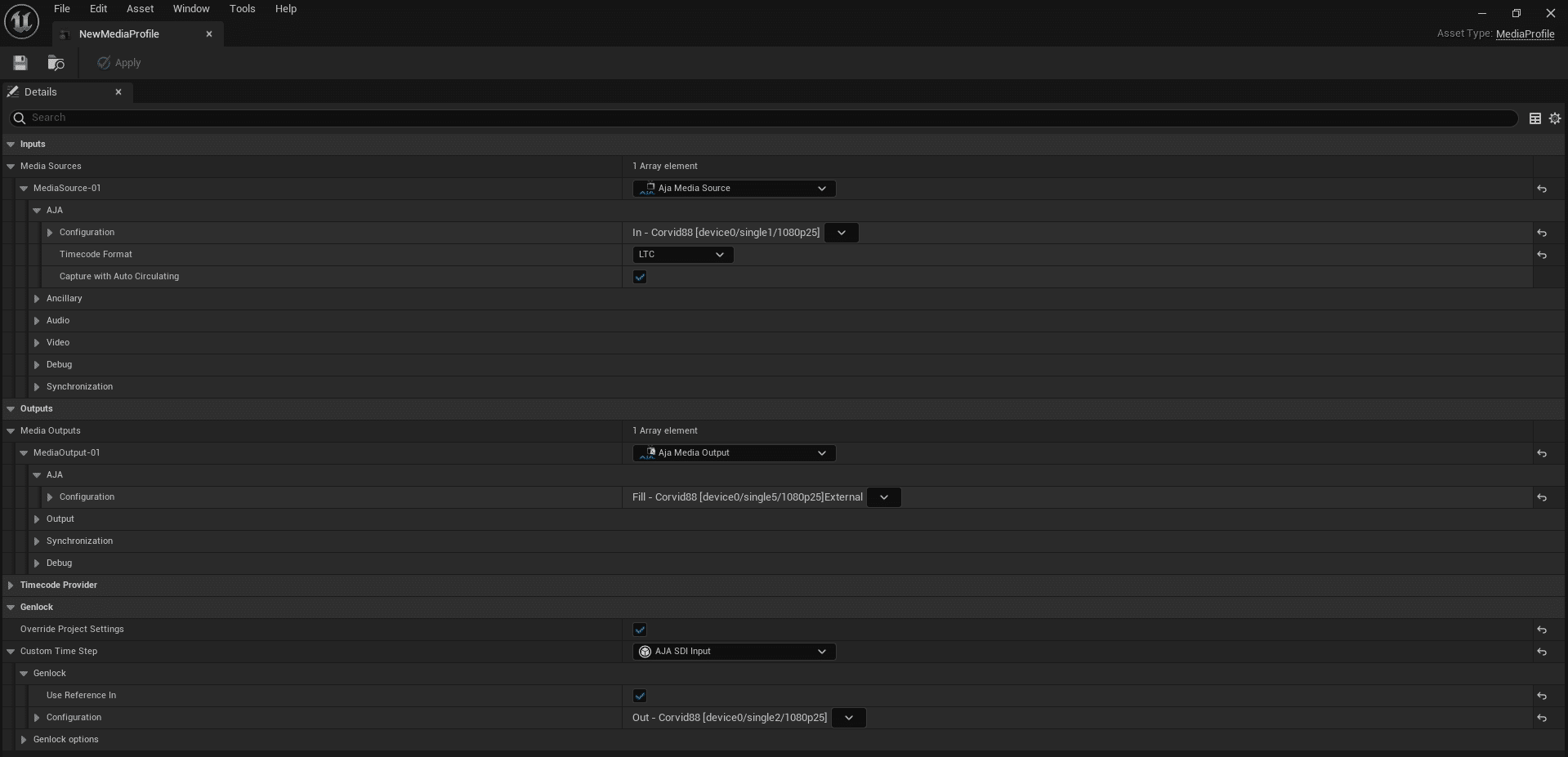
Here the configuration is for our Aja Corvid88 card. The unreal documentation uses a Decklink card as example, but the configuration options are very similar :
Basically we want to map the input to the right input pin with the right format, and the output to the right output pin with the right format. On top of this we need to overrid the genlock configuration so that the engine is synchronized on either the video or the external genlock coming into the acquisition card.
4.10.3 Start the Input Media Bundle
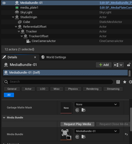
Creating the media profile has created a new « Media » folder in the content browser. Go inside it and look for a MediaBundle with the number coresponding to your input. Here we mapped input 1, so we want to use MediaBundle-01.
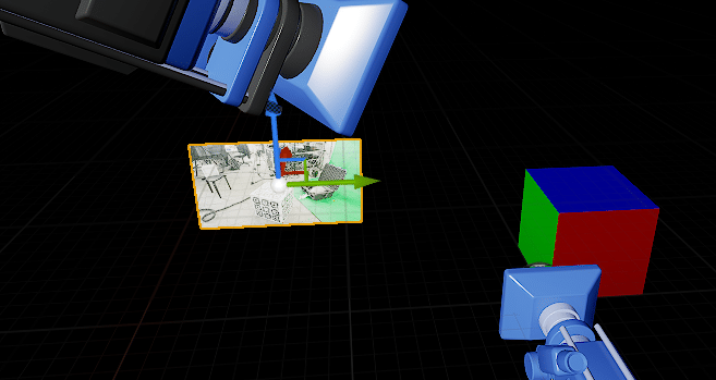
Drag and drop it into the scene, hopefully out of camera view. Press « Request Play Media » to start the video input. You should see the video appear on the MediaBundle plane and move when you move the camera:
4.11. Composure Setup
We now want to overlay the virtual cube on the real one. For this we will use the Composure plugin.
Create a simple hierarchy with a CGelement and a MediaPlate.
4.11.1. CG Element configuration
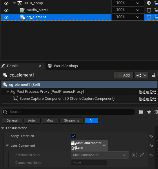
To apply distortion correctly, check « Apply Distortion » and select the correct CineCameraActor and LensComponent.
4.11.2. Media Plate Configuration
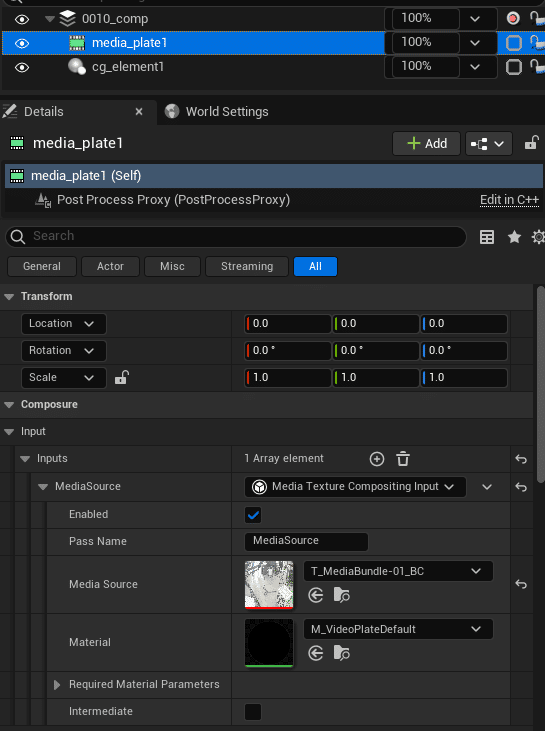
In the Media Plate, choose the Media Bundle. So long as the media bundle is running, the composure pipeline will receive video.
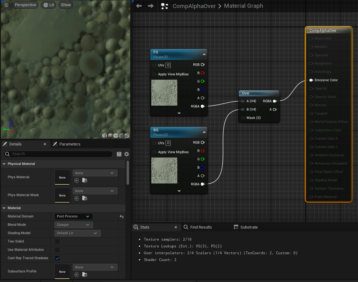
4.11.3. Media Composite Configuration
The composure material is a simple post-process with a composure Over node and two inputs, FG for foreground and BG for background :
In the main comp element, add a transform pass and select this material. Put the CG Element in FG and the MediaPlate in BG :
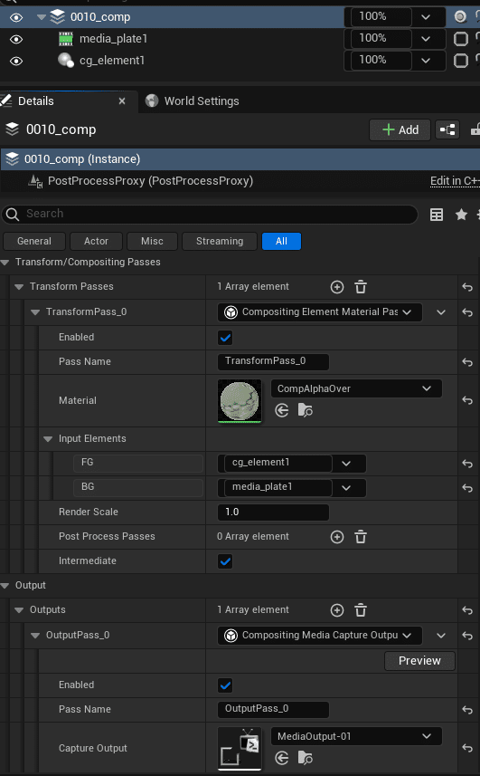
Here we also add an output to view the result on a SDI screen. Select the output proxy from the MediaProfile to do this.
4.12. Result
The resulting reprojection of the cube matches the reprojection in CalibFX® Lineup.