The main challenge of virtual production, and more precisely Augmented Reality (AR), is the necessity to generate computer generated images (CGI) that seamlessly blend with real-life footage. This is why great artistry and engineering goes into creating photorealistic assets, assembling a scene, matching the lighting, and performing a real-time rendering of it all. However all this work has to be seen through a virtual camera, and if the latter does not exactly match the real camera, the pictures will not line up correctly and everything will fall apart.
Thus the first step in a virtual production workflow is to model the characteristics of the real camera-lens assembly. It is the role of the camera tracking system to provide all the data necessary so that the render engine can produce an exact digital twin of the camera. These parameters are divided into two categories:
– Extrinsics define where the device is in the scene spatially. They correspond to position and rotation. Retrieving the pose of a camera is outside the scope of this article but we have another article that focuses on this part.
– Intrinsics model the inner working of the camera. They explain how the camera projects 3D objects onto a 2D image. Even though they don’t only depend on the lens, they are sometimes referred to as lens parameters.
The lens calibration is a process used to determines the intrinsic parameters. It leads to the creation of a lens profile that can be loaded into a render engine or a tracking device to convert measurements performed in real-time on the lens into meaningful quantities.
Lens calibration is one of the most essential yet sometimes overlooked aspects of a virtual production pipeline, as inaccuracies in the lens parameters have a direct effect on the projection of computer graphics (CG) over the real footage in the final image.
The purpose of this article is to list and explain the parameters needed to profile a camera.
First, the perspective projection model, used by most render engines, will be detailed. A second part will present post-processing effects used to replicate the physical artifacts of a real camera, followed by a discussion on the importance of the entrance pupil position. Finally we will discuss the dynamic representation of these parameters using Zoom, Focus and Iris encoders
The Perspective Projection Model
To realistically project a 3D object onto a 2D picture plane, the most widely used model is the Perspective Projection Model, also known as the Pinhole Camera Model.
The pinhole camera model is based on the historical camera obscura. All the light rays emitted by a real object pass straight through a single point in space, resulting in a flipped image of the object on a back plate.

The main advantage of this model is that the projection calculation can be done using only simple trigonometry, making it computationally inexpensive.
Field of View
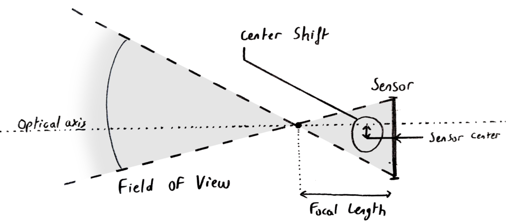
The distance between the pinhole and the backplate, also known as focal length, and the dimensions of the backplate, or sensor size, define the main parameters of this system. The field of view (FOV) of the camera is directly related to these two. It is an angle, often given in degrees, and corresponds to what is projected on the full effective area camera sensor area (the effective sensor size can be smaller than the full sensor size if the camera crops to change resolutions).
The FOV dictates the perspective projection of the camera, therefore in AR a miscalculated FOV will cause virtual objects to have vanishing lines that differ from that of a real object in the same orientation. Another effect is that a virtual object’s image will seem to glide over the footage as it follows a longer or shorter path than the real one on the sensor depending on whether the FOV is respectively larger or smaller.
Center Shift
The sensor is never perfectly centered on the optical axis of the lens. This is due to mechanical inaccuracies in the mounting alignment of the lens relative to the camera body. This misalignment is called center shift and has to be taken into account in the perspective projection.
When the focal length can vary, the zoom will be centered on the optical axis, thus offsetting the entire CG if the virtual camera zooms on the center of the sensor instead.
The center shift will change every time a lens is mounted, so it must be calibrated more often than the other parameters. Hopefully, it is constant across the entire zoom and focus range of a lens making this adjustment fast.
Post-Process Effects to Replicate a Physical Lens
The pinhole camera model works well as a basis, however a real lens is not that simple. Many artifacts occur with a physical camera. These define the look of the lens and they need to be replicated in the render engine. In a real-time workflow, this is usually done by applying post-process effects on the image rendered using the pinhole camera model.
Distortion
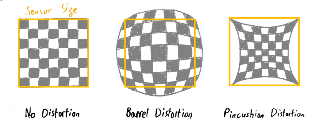
In a pinhole camera, the projection of parallel lines results in parallel lines on the sensor. On a real lens there are side effects near the border of the image where the shape of the lenses causes the light rays to go more inwards or outwards relative to the optical axis. This phenomenon is called distortion. The following illustrates the effect it has on the image:
In virtual production, the Brown-Conrady model is generally used to describe circular lens distortion. Most of the time, only K1 and K2, the first two radial components of the model, are considered. Additional parameters exist for more precision. K1 will have a relatively uniform effect while K2 is more impactful at the very edges of the image. Overall, the greater the value, the more the pixels get moved, the sign of the parameter telling whether to displace them toward the optical center or outward (respectively called pincushion or barrel distortion). Note that the radial distortion is centred around the optical axis, meaning that the center shift has to be calibrated for the distortion to be applied correctly, even with a prime lens.
Focus Distance and Depth of Field
The focus distance gives the position of the object plane, which is in perfect focus, relative to the camera sensor, and the depth of field describes the evolution of the zone in relatively good focus for closer and farther objects. By extension, the term depth of field is sometimes used for the evolution of the blur from the image plane to infinity:
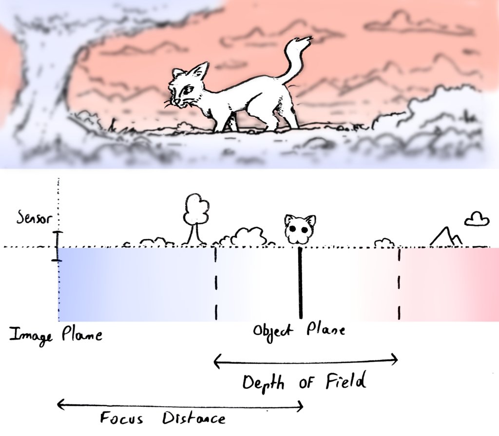
These parameters are intuitive for photographers, however, they are still the result of intricate adjustments within the lens. The camera sensor size plays a very important role for this effect, as the depth of field is affected by both the diameter of the aperture and the size of the sensor. At the same FOV and aperture, a smaller sensor will have a longer depth of field than a bigger one.
Matching the depth of field in AR thus requires knowledge of the exact sensor size of the camera. Most manufacturers give it in the manual, however some cameras crop on the sensor to adjust to different formats, which means the effective sensor size can be smaller than the one given.
Other effects
Other effects exist, most notably vignetting, chromatic aberrations and diffraction. They are usually not taken into account in a virtual production workflow and rendering engines as they are not as visually obvious, but models exist in the literature to describe them.
Entrance Pupil Offset
A physical camera-lens system is very complicated both mechanically and optically, yet it is absolutely possible to reproduce its effects using the parameters described in the previous sections.
However, to apply the perspective projection model, the position of the point through which all rays pass needs to be known. An imaginary point called the entrance pupil is defined as this center of perspective, and coincides with the pinhole in the special case of a pinhole camera. Geometrically, it can be seen as the vertex of the FOV cone, making it the perfect pivot point of the camera.
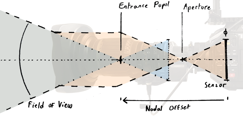
In blue: equivalent pinhole model
Usually, tracking providers use the sensor of the camera as a reference for extrinsics. So position and rotation are given for the intersection of the optical axis and the sensor plane. This means we need to estimate the distance between the sensor and the entrance pupil. This is called the Entrance Pupil Offset. A common synonym is Nodal Offset, although the term is based on a misconception and optically incorrect.
Depending of the focus or zoom settings, the location of the entrance pupil varies along the optical axis. The entrance pupil position is a virtual pinhole equivalent and has no physical meaning. For some lenses it can be positioned in front, out of the camera-lens body and sometimes behind the real sensor plane.
The entrance pupil offset is usually considered an intrinsic even though it describes a spatial position because it varies depending on the zoom and focus settings of the lens. It serves as a bridge between the spatial tracking and the camera model.
Dynamic representation
As highlighted in the previous section, all these parameters are in general not constant, and will vary depending on the position of the Zoom, Focus and Iris rings on the lens barrel. This means they have to be computed for every possible combination during the lens calibration process.
In general each parameter would be a tridimensional curve. Hopefully some assumptions are possible to reduce the complexity.
Firstly It is generally considered that sensor size is constant. Same with center shift.
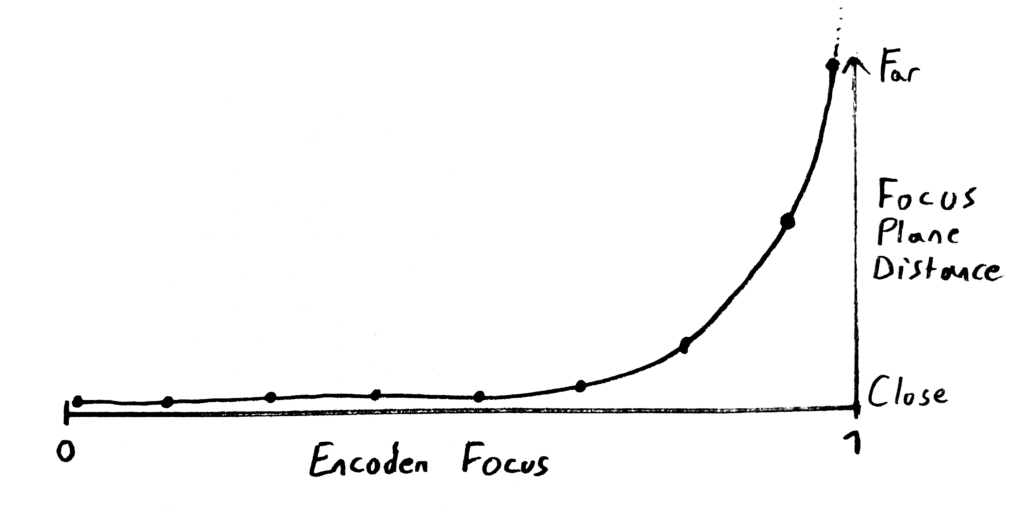
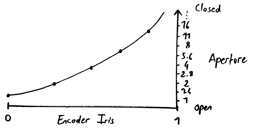
Then the aperture diameter is only affected by iris ring. So it means you can map iris encoder to f-stop as a 2d curve. With the same idea, Focus distance changes only with focus ring. It is the role of tweaking the backfocus on the flange to make sure this is the case.
Finally, the other parameters change with zoom and focus. For this reason, it is quite common to represent these parameters as a 3d surface. Ground plane represents the variation in zoom and focus rings, while elevation is the value of the parameters. Looking at the FOV, changes in zoom will obviously affect it a lot. Moreover, for some lenses a change in focus ring will also affect FOV, it is sometimes very noticeable visually and called breathing.
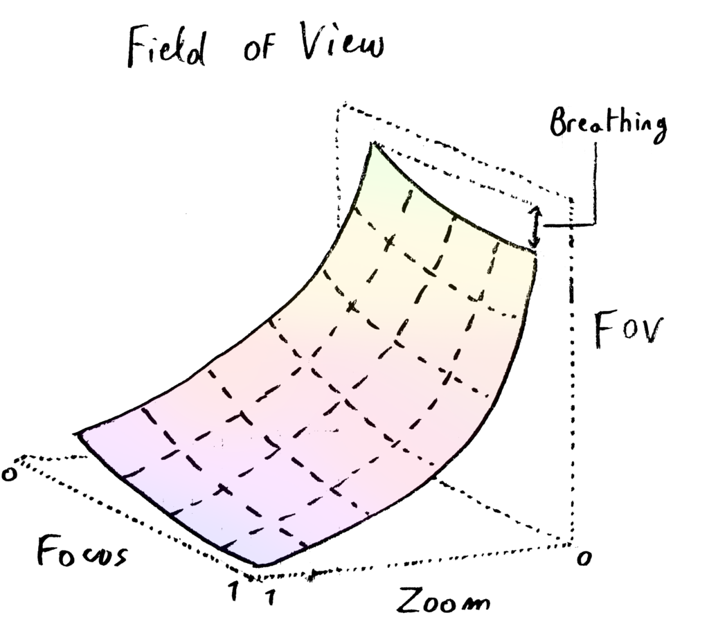
Distortion parameters and entrance pupil offset can also be represented this way.
Given a set of focus, iris and zoom position (FIZ data), a lens file will output all the calibrated lens parameters using the model previously described.
Lens Calibration using EZprofile
Lens calibration requires strong technical expertise and a lot of trial and error. To streamline and simplify the calibration process, we developed a lens calibration software called EZprofile, which enables users to quickly calibrate lenses from a broadcast zoom lens to a cine prime.
This solution is based on automated image processing, smart interpolation & fine-tuning of captured lens data. Once the calibration is completed (taking from few minutes to few hours depending on the lens) users can export their lens profile to multiple real-time 3D engines like Unreal, Zero Density, Vizrt, Aximmetry and Pixotope. It is a standalone solution, meaning it supports any camera tracking system that outputs raw lens data using the FreeD protocol.
Bibliography
Physically Based Rendering: From Theory To Implementation,
M. Pharr, W. Jakob, G. Humphreys
https://pbr-book.org/3ed-2018/Camera_Models/Realistic_Cameras
Theory of the no parallax point,
R. Littlefield
https://www.janrik.net/PanoPostings/NoParallaxPoint/TheoryOfTheNoParallaxPoint.pdf
Implementation of the DoF post-processing in Vizrt,
https://documentation.vizrt.com/viz-artist-guide/5.0/Cinematic_Depth_of_Field.html