Glossary
1. Raw Data
1.1. Encoder data
Raw lens data is obtained from an encoded lens, that is a lens that can send metadata reflecting its state in real time. While some high-end lenses provide calibrated data directly, most either give an arbitrary uncalibrated value or don't encode data themselves so that external rotary encoders have to be placed on the lens barrel to capture the rotation of the controls.
A hub like EZtrack can be connected to electronically read the encoder values from the lens and send them over the network to a rendering computer in a lens-manufacturer-agnostic format using one of the following protocols:
1.2. FreeD protocol
In real-time applications, the most widespread protocol for raw tracking data transmission is FreeD. This is one of the protocol EZprofile uses as input. It contains the following fields:
| Parameter | Format | Precision |
|---|---|---|
| X | Integer | 24 bits |
| Y | Integer | 24 bits |
| Z | Integer | 24 bits |
| Pan | Integer | 24 bits |
| Tilt | Integer | 24 bits |
| Roll | Integer | 24 bits |
| Zoom | Integer | 24 bits |
| Focus | Integer | 24 bits |
FreeD is also the protocol most tracking systems use to send data to render engines currently. Since Zoom and Focus are encoded as 24 bit integers, the render engine can not deduce even the basic camera intrinsics like focal length and focus distance from these values directly. Usually they all have their own lens profile format to perform the conversion.
The goal of EZprofile is to provide a unified worflow to create these lens profiles, mapping the raw encoder values to the following calibrated quantities.
1.3. TCD protocol
Miraxyz develops its own protocol called TCD (Tracking Calibrated Data). There are multiple possible formats depending on the data to send. In addition to calibrated data (Field of View, Focus Distance, Aperture, etc...), all data frames also carry raw information, so encoder Zoom, Focus, and Iris.
This means it is possible to calibrate the aperture (in f-stop) as a function of the iris encoder value in EZprofile using TCD as the input protocol.
2. Camera Specifications
2.1. Sensor Size
The Sensor Size is the dimensions of the camera sensor. You can find this information in the user manual of your camera. If you don't find it, you can also try looking on https://vfxcamdb.com/.
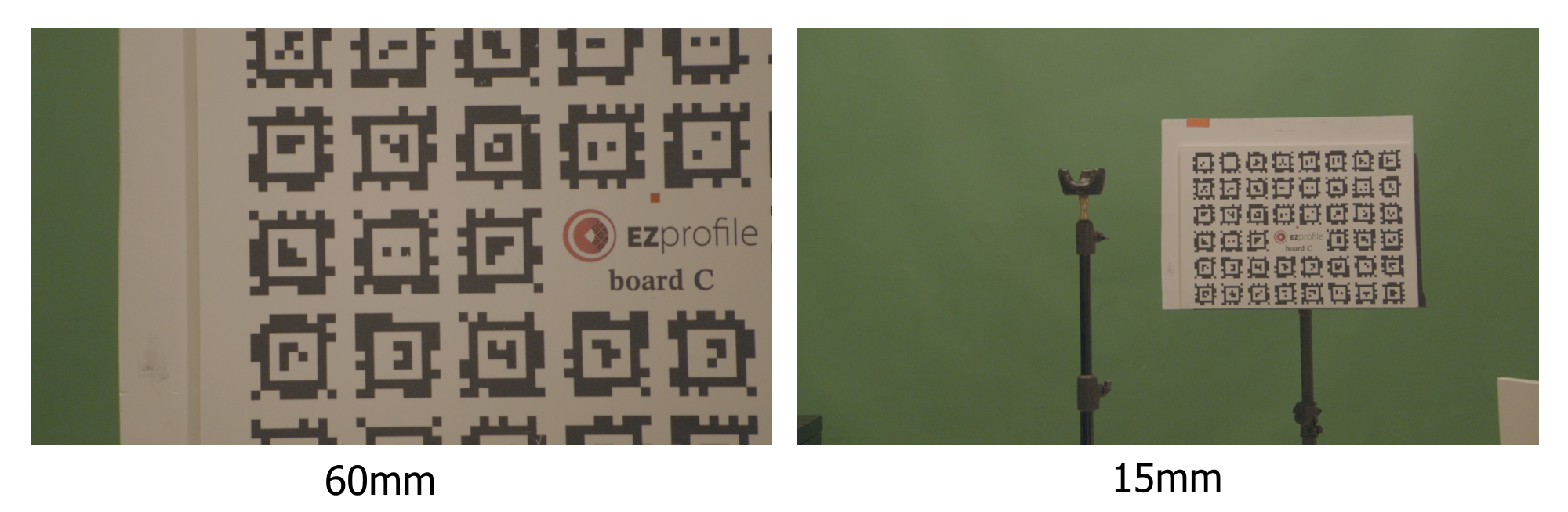
2.1.1. Sensor Size influence on field of view
The sensor size is used in the conversion between focal length and field of view:
In practice, this means the same lens will give a narrower field of view on a smaller sensor:
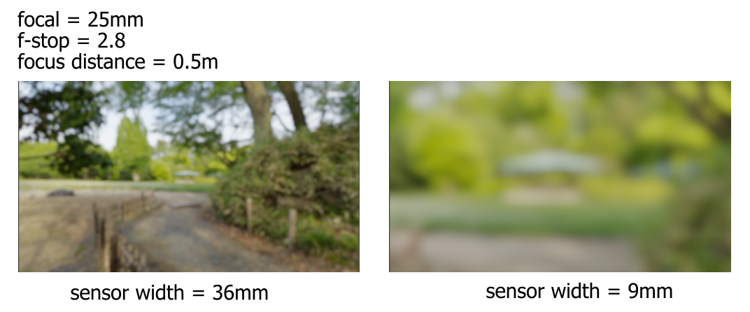
For this reason, since most render engines use focal length in their lens profiles rather than FOV, you have to make sure that the sensor size in EZprofile is the same as the sensor size in the render engine, otherwise the field of view in the CG footage will not match the video.
2.1.2. Sensor Size influence on depth of field
The same field of view will give a shallower depth of field on a larger sensor:
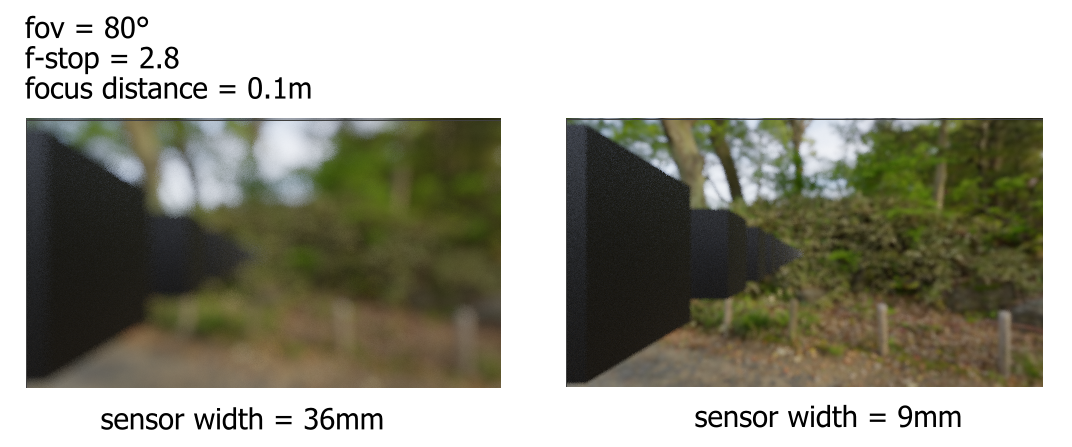
For this reason, you should put the actual sensor size in both EZprofile and the render engine. If you put 36mm for a 9mm broadcast camera, the depth of field will look wrong.
2.2. Resolution
The Resolution is the size of the input footage. It is used in many conversions while computing other coefficients. The exports are resolution-independant, so a lens calibration done in HD can be used for 4K.
Warning
some cameras crop the footage between resolutions. In this case, there will be issues with the sensor size as the effective sensor size is not the size given by the manufacturer. It is sometimes possible to calculate the effective sensor size with a cross-multiplication on the resolutions.
3. Camera Instrinsics
3.1. Center Shift
The Center Shift \((c_x, c_y)\) is the offset between the optical center and the camera sensor center. It may be due to a variety of factors but overall it results from a normal imperfection in the alignment between the sensor and the lens.
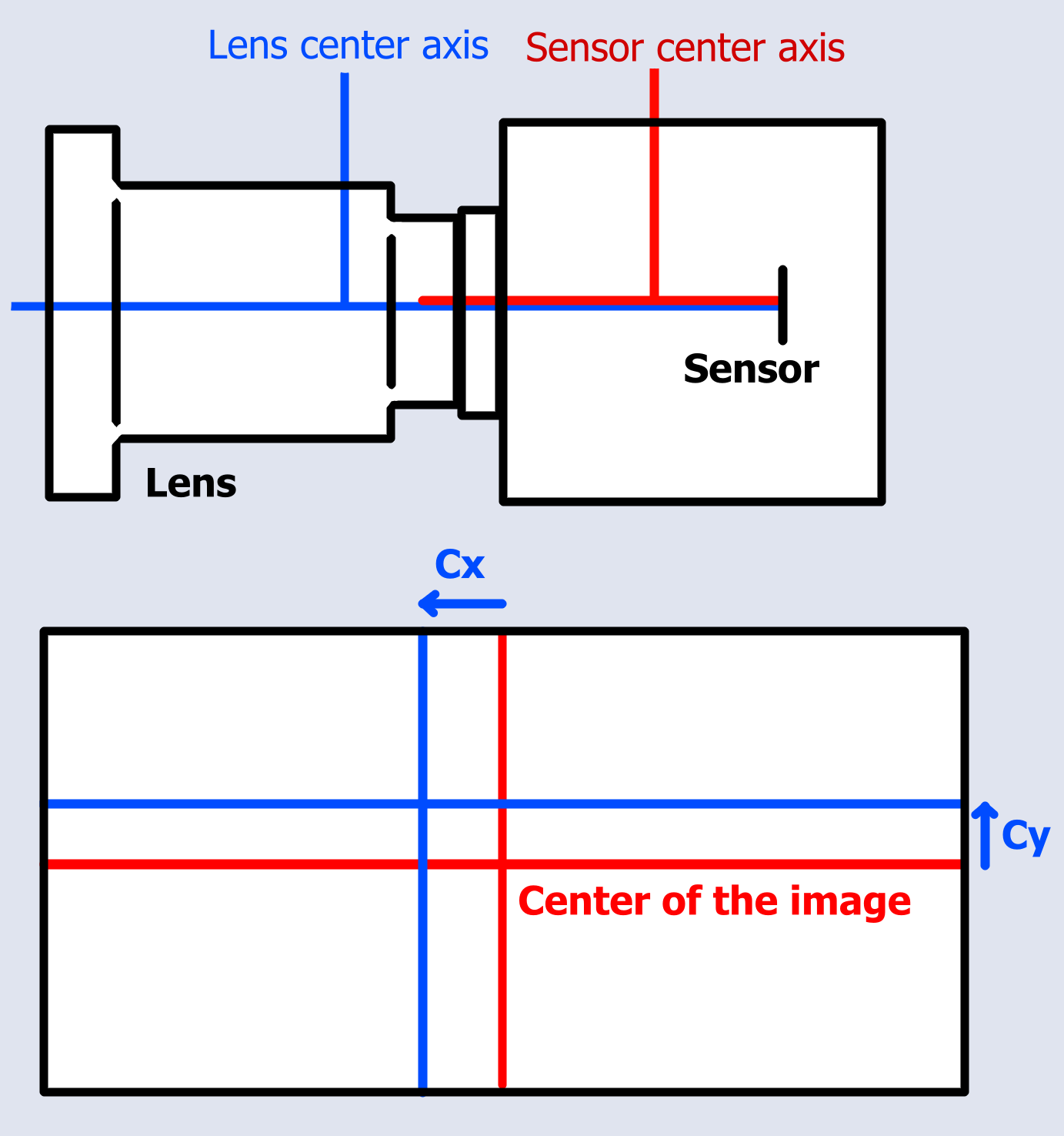
this parameter has no influence on the tracking itself as the position of the virtual camera is only shifted by a very small distance, however the zoom and distortion are applied around the lens optical center, so without calibrating the centershift there is a noticeable offset between the footage and the AR.
In EZprofile, it is expressed in pixels from the center.
3.2. Field of View
The Field of View is the angle the camera sees.
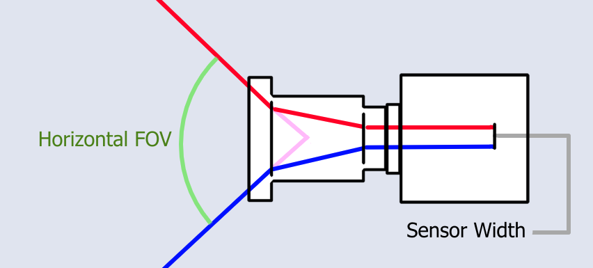
The field of view is obtained from the focal length with the formula:
This is the most important parameter as it will dictate the entire perspective of the rendered view. If the FOV is wrong, everything will look wrong.
3.3. Distortion (K1, K2)
The Distortion warps the image, with a stronger effect on the image borders and almost no effect near the center of the video. Distortion is applied in 2D on CGI rendered efficiently with a pinhole camera to match that of the real footage. The distortion model used in EZprofile is a simplification of the Brown–Conrady model for spherical lenses:
where \(P\) is the pixel coordinate of a point in the image.
To visualize the effect of the K1 coefficient:
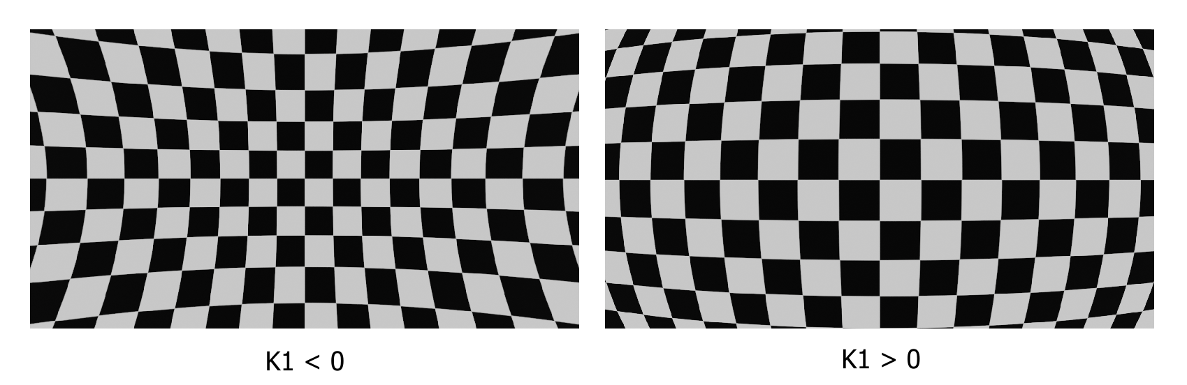
K2 has a similar effect, but stronger near the borders than for K1. The combination of the two approximates well spherical distortion.
Warning
It is not possible to calibrate anamorphic or fish-eye lenses with EZprofile.
Note
The distortion model also has \(k_3\), \(p_1\) and \(p_2\) coefficients. They are negligible for this application, especially in lenses that are relatively well built. Also, most render engines do not support them.
3.4. Focus Distance
The Focus Distance is the distance to the entrance pupil at which objects are perfectly sharp. They are progressively blurred closer and farther. This blurring occurs non-linearly, leaving a segment in relatively good focus called the depth of field. The depth of field curve depends on the sensor size.
Note
The bokeh out of focus can vary in shape depending on the optics compared to the standard circle. This is purely cosmetic and can be tweaked manually in the render engine.
4. Camera Extrinsics
4.1. Nodal Offset
The Nodal Offset, or Entrance Pupil Distance, is the offset of the Entrance Pupil relative to the sensor plane along the optical axis.
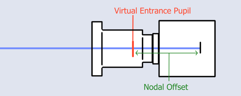
The nodal offset can move quite a lot when zooming and changing focus as the internal components of the lens move to compensate for other characteristics. Usually for common focal lengths it falls between 30cm in front and 10cm behind the sensor.
In the realm of AR, this position is extremely important since it is the point at which a pinhole camera's aperture must be placed for this model to work as a good approximation of the real optics. When tracking, it can offset quite strongly the position of the virtual camera compared to the sensor position which the tracking gives. A wrong nodal offset will be quite noticeable in pan and tilt motions, with less effect as the objects get further toward infinity, as the nodal offset becomes negligible at very long distances.