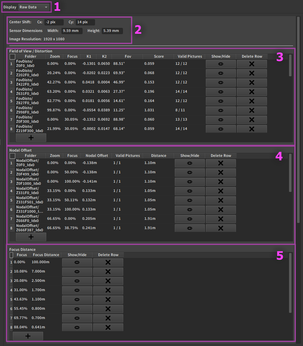
Raw Data Table
Tip
Apart from the resolution of the calibration, all values are editable by hand
1. Middle section display selector
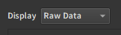
This allows choosing between all 3 available middle sections:
2. Constant parameters
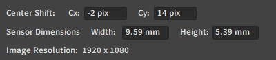
2.1. Center Shift
Cx and Cy are given in terms of pixels relative to the center of the image. While the center shift is resolution independant in the exports, it is not inside EZprofile.
2.2. Sensor Dimensions
The dimensions of the camera sensor in millimeters. They are used at export time along with the corresponding pixel resolution to perform conversions in the exports.
2.3. Image Resolution
This is the pixel resolution of the calibration. It is used in conversions. It corresponds to the resolution of pictures in the dataset. If no pictures were taken, the input resolution parameter at the time of the calibration is taken.
3. Field of view / Distortion table
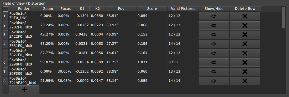
3.1. Folder
The path to the folder containing the pictures corresponding to this point in the dataset.
3.2. Zoom and Focus
The encoder Zoom and Focus value for that point, normalized between 0% and 100%. They can be seen as the coordinates of the calibration point in the Zoom/Focus plane. Keeping this in mind is useful to understand and navigate the graphs at the Refine Step.
3.3. K1 / K2 / Fov
Calibrated parameters for distortion and field of view. K1 and K2 are displayed in OpenCV space in this table, and the field of view is in degrees.
3.4. Score
The score is a measure of how good the calibration is for a given point. The lower the score the better.
Note
Usually a score higher than 0.5 is suspicious, but not necessarily wrong.
The best way to use this score is in conjunction with the Refine Graphs. If a point seems to be an outlier on the graph and has a high score,
deleting or editing it will make the calibration better.
in the example table above, row 6 has a high score and thus a high chance to be wrong.
3.5. Valid Pictures
Given as number of valid pictures over total number of pictures for the point.
If a picture has too few detected tags, it will be ignored.
Note
Clicking on the row will open the corresponding pictures in the browser on the right. You can check there which pictures are not valid.
3.6. Show/Hide
Hide the row in the interpolation and the export. It does essentially the same as the Delete Row button but non-destructively.
3.7. Delete Row
Deletes the calibration point. It will not appear in further steps from pressing the button on.
Danger
the data is destroyed by this operation, use Show/Hide if the point seems salvageable.
4. Nodal Offset table
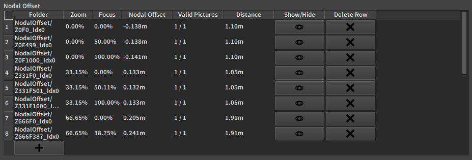
4.1. Nodal Offset
Calibrated nodal offset. It is the difference between the estimated distance from the picture and the measured distance. It is expressed in meters.
Warning
The nodal offset estimation depends on the field of view and distortion coefficients. Modifying values in the fov/disto table will update the nodal offset table.
If a nodal offset value is manually edited, it will no longer be updated by fov/disto.
4.2. Distance
Distance measured by the user between the sensor and the board in meters.
5. Focus Distance table
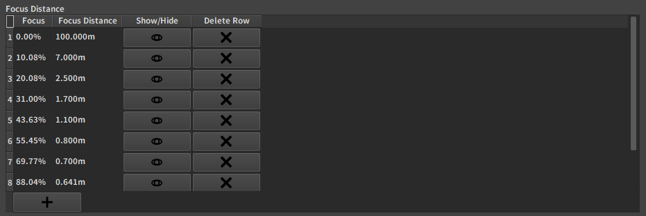
5.1. Focus Distance
Distance measured by the user between the sensor and the object in focus in meters.
Warning
You most likely won't be able to go to infinity to calibrate the focus distance there. Therefore for every calibration you should manually add a point at the encoder value corresponding to infinity focus and put a large value there, like 50m, or 100m, depending on the size of your set. It should not be absurdly large or the interpolation will break.